11
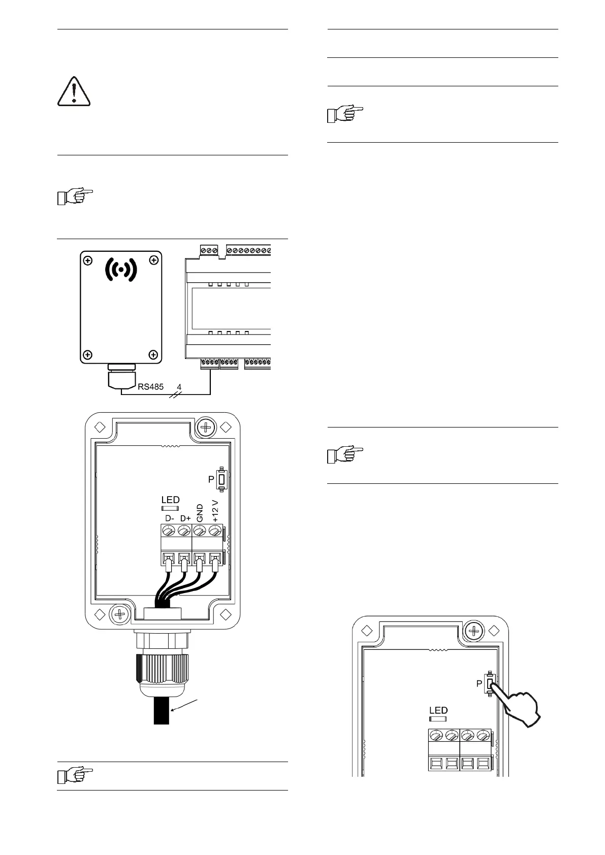
When connecting the transmission
and power supply attention should
be paid to the proper polarity of
connection of D +, D- and GND, 12
VDC between the radio module and
the main controller. Improper
connection may lead to damage to
the main controller or errors in its
operation.
The maximum cable length depends
on the cross-section of the wires.
For a 0.5 mm
2
wire, it should not
exceed 30 m. The cross-section
should not, however, be less than
0.5 mm
2
.
11.2 Pairing the radio module with the
wireless room panel
The radio module connected
electrically to the main controller
requires pairing with a wireless
room panel.
Pairing from the main controller menu:
The pairing method is only available
when the main controller program is
fully compatible with the radio
module.
Enter the main controller menu:
MENU → General settings → Radio
module → Pairing mode → Device pairing
mode and set the Start pairing? to Yes, then
the pairing mode will be activated for 4
minutes, during this time the room panel
with the radio module should be paired, in
accordance with point 8.11.12.
During the active pairing mode, you can pair,
in the same way, subsequent wireless room
panels.
After correctly pairing the room panels with
the radio module, end the pairing mode in
the main controller menu or you can wait for
the active pairing time to expire.
After establishing the radio connection with
the room panel in the main controller
Information menu, the panels will be
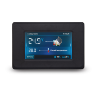
shown as eSTER_x80, with the version of the
software displayed.
Connecting the radio module to the
master controller again does not
require pairing if the room panels
have previously been paired.
Pairing directly from the radio module:
With limited compatibility of the main
controller program with the radio module,
the P button of the radio module is used to
start the pairing mode, which should be
briefly pressed once - then the LED will start
to flash, which means that the pairing mode
will be activated for 4 minutes.
4x0.5 mm
2
wire,
max. length 30 m
Assembly screw