13
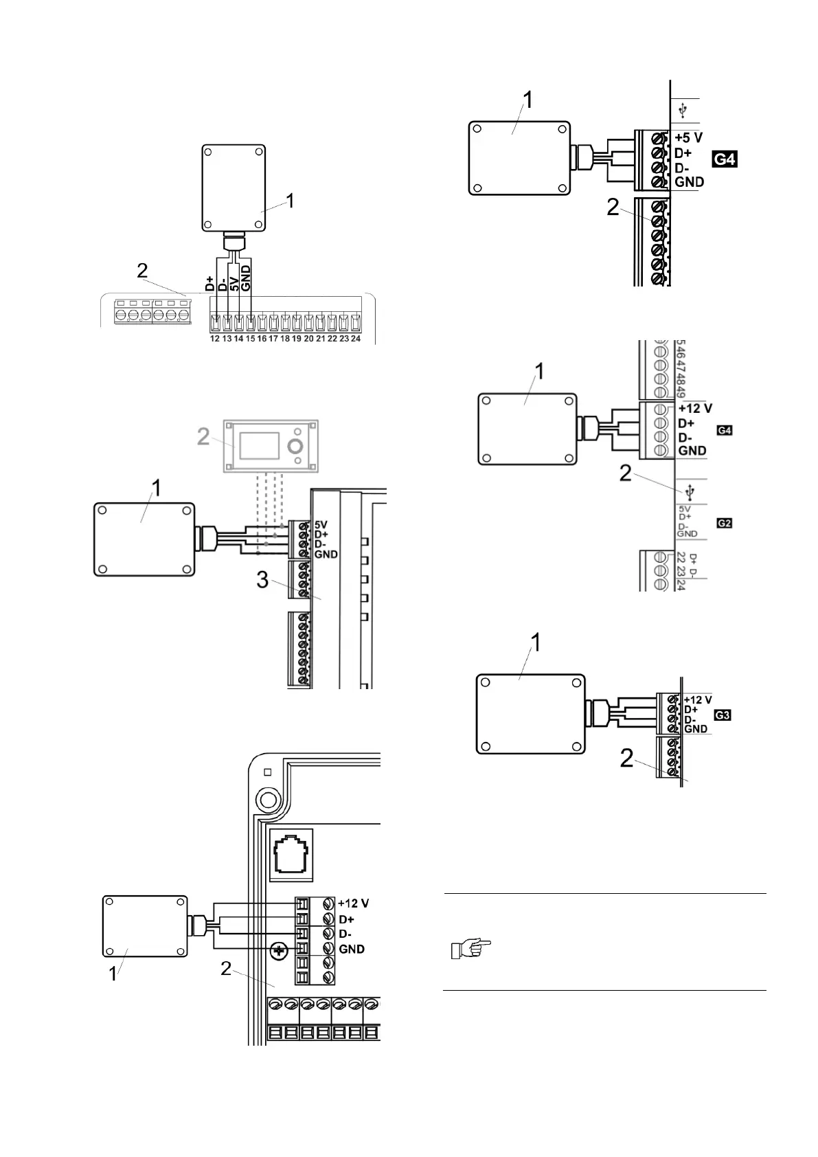
11.5 Connecting the radio module to
selected main controllers
The electrical schemes of the radio module's
electrical connections to the main controller's
terminals are shown below.
Connection of the module to the ecoMAX350P1,
P2, R1, R2: 1 – radio module, 2 – main
controller.
Connection of the module to the ecoMAX800P3,
D3 and ecoMAXX800R3, T3: 1 - radio module, 2
– control panel, 3 – main controller.
Connection of the module to the ecoMAX850P2,
R2, D2: 1 - radio module, 2 – main controller.
Connection of the module to the ecoMAX860P1,
P2, D1, D2: 1 - radio module, 2 – main
controller.
Connection of the module to the ecoMAX860P3,
D3: 1 - radio module, 2 – main controller.
Connection of the module to the ecoMAX910R1,
ecoMAX920P1: 1 - radio module, 2 – main
controller.
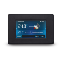
12. Connecting the room panel to the
terminals of the main controller
When wired RS485 transmission
signals between the wireless room
panel and the main controller, the
room panel does not use radio
transmission.
Below are the schemes of connecting the
electric wireless room panel directly to the
terminals of the main controller, without
radio transmission.