4
GOLD 1-3 SK-GB-708
Right to make modifications without prior notice
2. ELECTRICAL CONNECTION
2.1 Power
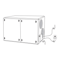
Units in sizes 1 and 2 are connected with factory installed
electrical plug, otherwise permanently connected to
single phase 230V, 50Hz, 10A.
For size 3 permanent connection applies, 2 x 230 V + N,
50 Hz, 2 x 10 A.
2.2 Safety
Lockable isolator switch is located on the control enclo-
sure.
2.3 Display
The display is connected to the unit via contact on the
factory mounted cable on the display.
2.4 Supply air sensor
The sensor is fixed into the supply air duct at a distance
of at least 5 x the duct diameter from the unit or possible
reheater. Shall always be mounted after coil.
2.5 Reheater
2.5.1 Electrical heater
Power supply shall be carried out through working switch
directly from distribution box.
Unit size 1 2,0 kW, 2-phase 400 v + earth, 5,0 A.
Unit size 2 3,6 kW, 2-phase 400 V + earth, 9,0 A.
Unit size 3 6,0 kW, 3-phase 400 V + earth, 8,7 A.
Control signal to the built-in thyristor is connected to the
unit via a quick coupling on the factory mounted cable on
the electrical heater.
Alarm from the overheating protection is transferred to
the unit and shown on the display.
Possible reset of alarm is done on the battery and the
display.
At stopped unit cooling is carried out when necessary.
2.5.2 Watercoil
The control signal to the valve + actuator is connected to
the unit via a quick coupling on the pre-connected cable
to the actuator.