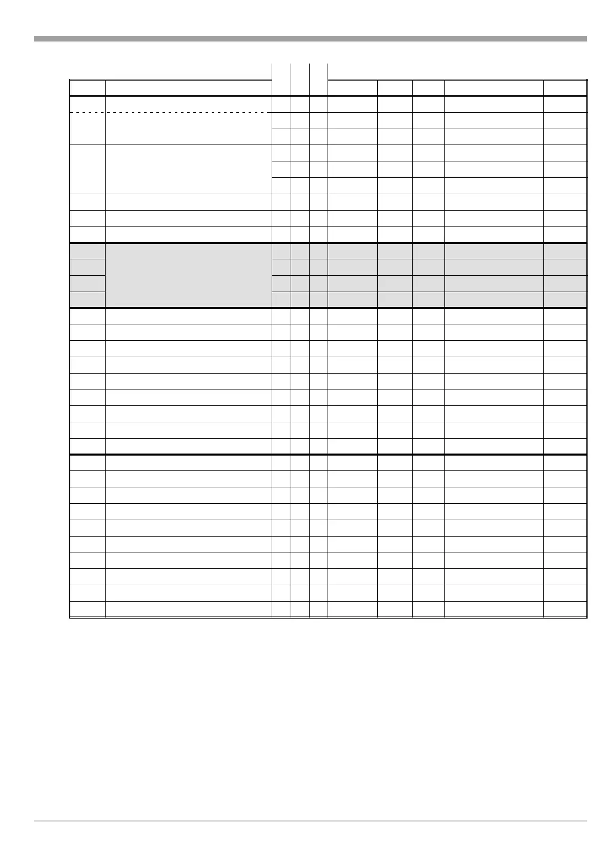
KS KS KS
CODE Description 40 50 90 Disp R/W Len. Value range Rem.
51 2nd set-point or
fff
SP2
R/W 9 SPL... SPH/- - - -
#>
52
Set-points for programmer
fff
SP3 R/W 9 SPL... SPH
53
fff
SP4 R/W 9 SPL... SPH
54
Segment times for programmer
fff
Pt2 R/W 7 0...9999
55
fff
Pt3 R/W 7 0...9999
56
fff
Pt4
R/W 7 0...9999
57 5th set-point (programmer)
fff
SP5 R/W 9 SP L ... SPH
58 5th segment time (progr.)
fff
Pt5 R/W 7 0...9999
59 Gradient
fff
Gr R/W 8 0.1...999.9 /- - - -
>
q
61
Configuration level
fff
Con1 R7
q
62
fff
Con2
R7
q63 -
ff
Con3 R7
q
64 --
f
Con4 R7
71 Correcting variable for start-up -
ff
YA R/W 6 5...100
72 Set-point for start-up -
ff
SPA R/W 9 SPL... SPH
73 Holding time for start-up -
ff
PtA
R/W 7 0...9999
74 Max. correct. variable average -
f
- YH R/W 6 5...100
75 Limit for averaging (corr. var.) -
f
- LYH R/W 7 0.1...10.0
76 2nd correcting variable - -
f
Y2 R/W 6 YLL... YLH
77 Filter time constant - -
f
tF R/W 8 0.0...999.9
78 Span start
fff
InL R/W 9 999...( InH - 1)
y
79 Span end
fff
InH R/W 9 ( InL + 1)...9999
y
81 Decimal point
fff
dP R/W 4 (dP)
<
82 Lower set-point limit
fff
SPL R/W 9 InL...( SPH - 1)
83 Upper set-point limit
fff
SPH R/W 9 ( SPL + 1)... InH
85 Lower output limit - -
f
YLL R/W 7 -100...( YLH - 10)
86 Upper output limit - -
f
YLH R/W 7 ( YLL + 10)...100
87 Cycle time heating
fff
t1 R/W 8 0,4...999,9
88 Cycle time cooling
fff
t2 R/W 8 0,4...999,9
89 Operation locking
fff
Loc R/W 4 (Loc)
<
B2,01 Set-points SP2... SP11 --
f
R/W 80/83 SPL... SPH
Ü
B2,02 Segment times Pt2... Pt11 --
f
R/W 60/63 0...9999
Ü
Ü Block access (Ä chapter 3.1, General structure and chapter 6, Communication examples)
* KS 40 / KS 50: (Y) can be read only.
KS 90: Y can be read and written. The written value becomes valid in manual mode.
Ö The process value is only valid, if bit 3 and bit 5 in status byte 1 are 0 (no sensor or polarity error).
äÄ chapter 7, Remote/Local operation
# With KS 40 / KS 50 positioners: output signal (–100%) / 0%...100%, no switch-off function.
< The limits of these values depend on the instrument (Ä data sheet or operating instructions).
> If four minus signs are transmitted, the relevant function is switched off.
y These values can be written only with standard signal input. They must not be changed with running
programmer or ramp (Ä NAK).
English CODE table
960612 5 Interface description 9499 040 47701
 Loading...