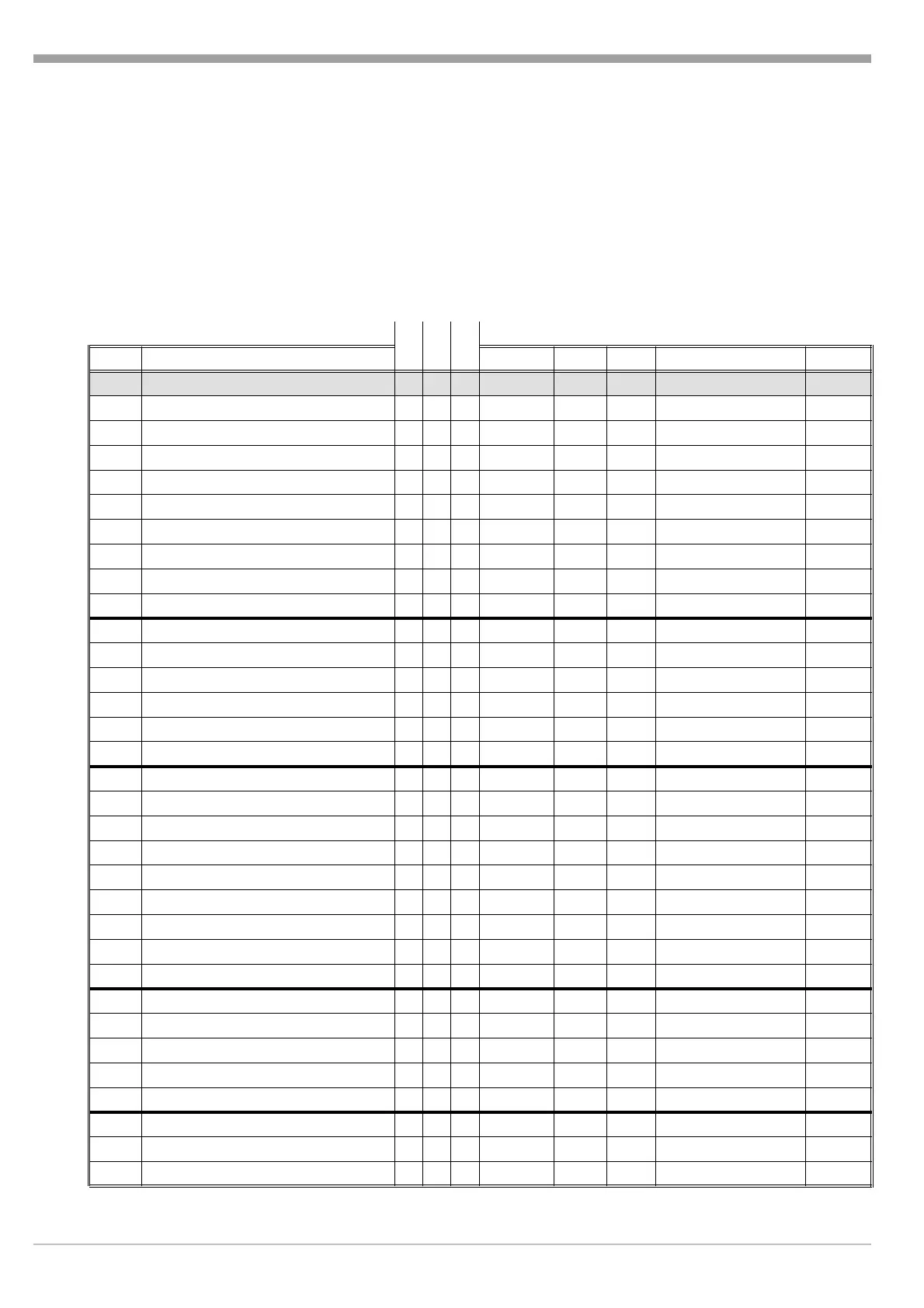
4 CODE table
The table shows the CODEs for data transmission. Two data types are permitted:
q For the two status bytes: 1 Byte, bit-oriented
q For all other data: Decimal digits, with decimal point and/or minus sign, each ASCII-coded
Explanation of columns:
Disp: Messages displayed by the controller (symbols in brackets are not displayed)
R: Read data from controller (Local/Remote)
W: Write data to controller (Remote)
Len: max. number of bytes between STX and ETX (DATA)
KS KS KS
CODE Description 40 50 90 Disp R/W Len. Value range Rem.
q
00 Operating level
fff
R 40/46
Ü
01 Status byte 1
fff
(ST1) R 4
02 Status byte 2
fff
(ST2) R 4
03 Correcting variable
fff
(Y) Y R/(W) 7
*
04 Setpoint effective
fff
(W) R 9
05 Process value
fff
(X) R 9
Ö
06 Setpoint volatile
fff
(W
vol
) R/W 9 SPL... SPH/- - - -
ä#>
07 Setpoint non-volatile
fff
(W
nonvol
) R/W 9 SPL... SPH /- - - -
ä#>
09 Heating current
ff
- HC R7
09 2nd process value - -
f
(X2) R 9
11 Controller active / not active - -
f
- R/W 4 0 / 1
12 Y2 active / not active - -
f
- R/W 4 0 / 1
13 Manual mode active / not active - -
f
- R/W 4 0 / 1
14 2nd set-point active / not active - -
f
- R/W 4 0 / 1
15 Wext active / not active - -
f
- R/W 4 0 / 1
19 Ydiff - -
f
- W 7 -205...205
21 Proportional band heating
fff
Pb1 R/W 8 0.1...999.9
22 Proportional band cooling
fff
Pb2 R/W 8 0.1...999.9
23 Integral time
fff
ti R/W 7 0/1...9999
24 Derivative time
fff
td R/W 7 0...9999
25 Actuator response time
f
-
f
tt R/W 6 (tt)
<
26 Alarm switching differential (1)
fff
Sd(A1)
R/W 9 1...9999
27 Trigger point separation
f
-
f
SH R/W 7 0.2...20.0%
28 Alarm switching differential (2) - -
f
SdA2 R/W 9 1...9999
29 Zero offset (ratio control) - -
f
OFFS R/W 6 -20...0...20
31 Limit contact low (1)
fff
LCL(1)
R/W 9 1/ InL...9999/- - - -
>
32 Limit contact high (1)
fff
LCH(1)
R/W 9 1/ InL...9999/- - - -
>
35 Limit contact low (2) -
ff
LCL(2)
R/W 9 1/ InL...9999/- - - -
>
36 Limit contact high (2) -
ff
LCH(2)
R/W 9 1/ InL...9999/- - - -
>
39 Signaller switching differential - -
f
SdS R/W 9 1...9999
47 Heating current limit
ff
- HCA R/W 7 (HCA)/- - - -
<>
48 Heating current range -
f
- HCH R/W 7 1.0...99.9
48 Min. step time - -
f
tt P R/W 6 0.1...2.0
CODE table English
Interface description 9499 040 47701 4 960612