36
CONTROL SYSTEM NAVIGATION
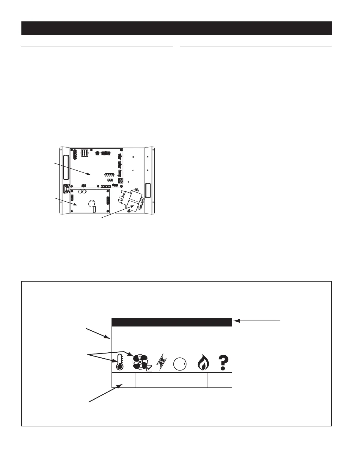
All operational information and user settings are displayed and
accessed from the UIM. The UIM houses the control system’s LCD
Touch Display (liquid crystal display). See Figure 40 below.
THE DESKTOP SCREEN
During normal operation the control system will display the
“Desktop” screen on the LCD Touch Display which is the default
screen. The control system will return to the Desktop screen when
there are no active Fault or Alert conditions or when there has
been no user input for several minutes.
• Manufacturer and water heater model information is
displayed in Title Bar at the top of the Desktop screen. Menu
titles are displayed in the Title Bar when navigating the
control system menus.
• The temperature shown on the Desktop screen is the
Operating Set Point. The Operating Set Point is the
temperature at which the control system will maintain the
water inside the storage tank.
• Beneath the Operating Set Point is the “Status” line. The
Status line shows the current operational state of the control
system in real time, see Table 13 on Page 38 for a description
of the various operational states.
• The Desktop screen also displays animated “Status Icons” to
convey operational information, see Table 12 on Page 37 for
descriptions of the Status Icons.
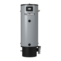
OVERVIEW
The water heaters covered in this manual are equipped with an
electronic control system that regulates water temperature inside
the storage tank. Heating cycles and ignition are managed by the
control system. The ECO (energy cut out), ame sensor, pressure
switches and temperature probes are monitored by the control
system. The Combustion Blower, Spark Ignition Transformer, 24
Volt Gas Control Valve are all powered by the control system.
The main components of the control system are a UIM (user
interface module) and a CCB (central control board). The UIM is
located on the top front side of the water heater. The CCB is mounted
on the base of the water heater inside a protective enclosure, see
Figure 39. This unit is equipped with an Enable/Disable switch. To
operate unit, make sure the switch is set to Enable. See Features
and Components beginning on Page 11 for location of these and
other water heater components.
POWER
SUPPLY
BOARD
TRANSFORMER
CCB
BOARD
Figure 39
Figure 40
CONTROL SYSTEM OPERATION
Operating Set Point 120°F
Status: Heating
GAS
OFF
O
N
HELPMENU
LCD Touch Display
Information
Display
Status Icons
Title Ba
Operational menus are multi functional.
UIM (user interface module)
Desktop Screen Shown
 Loading...