45
INITIAL START UP
REQUIRED TEST EQUIPMENT
• One U-tube manometer, recommended ranges; 0-14” W.C. (0-
3.5 kPa) and 0-35” W.C. (0-8.7 kPa) or pressure gauges.
• One digital manometer can be used in place of U-tube
manometers or pressure gauges. Recommended ranges;
-14.00 to +14.00” W.C. (0-3.5 kPa) resolution 0.01” W.C. and
0-35” W.C. (0-8.7 kPa) resolution 0.10” W.C.
NOTE: All test equipment must be acclimated to ambient
temperature before calibration and use.
PREPARATION
1. Using the control system menus, change the Operating Set
Point to the lowest temperature setting, see Operating Set
Point And Differential Adjustment on page 39.
2. Turn the water heater’s Enable/Disable switch to the “Disabled”
position.
3. Close the manual gas shut off valve, see Figure 37 on page 31.
4. Wait ve (5) minutes for any residual gas to clear.
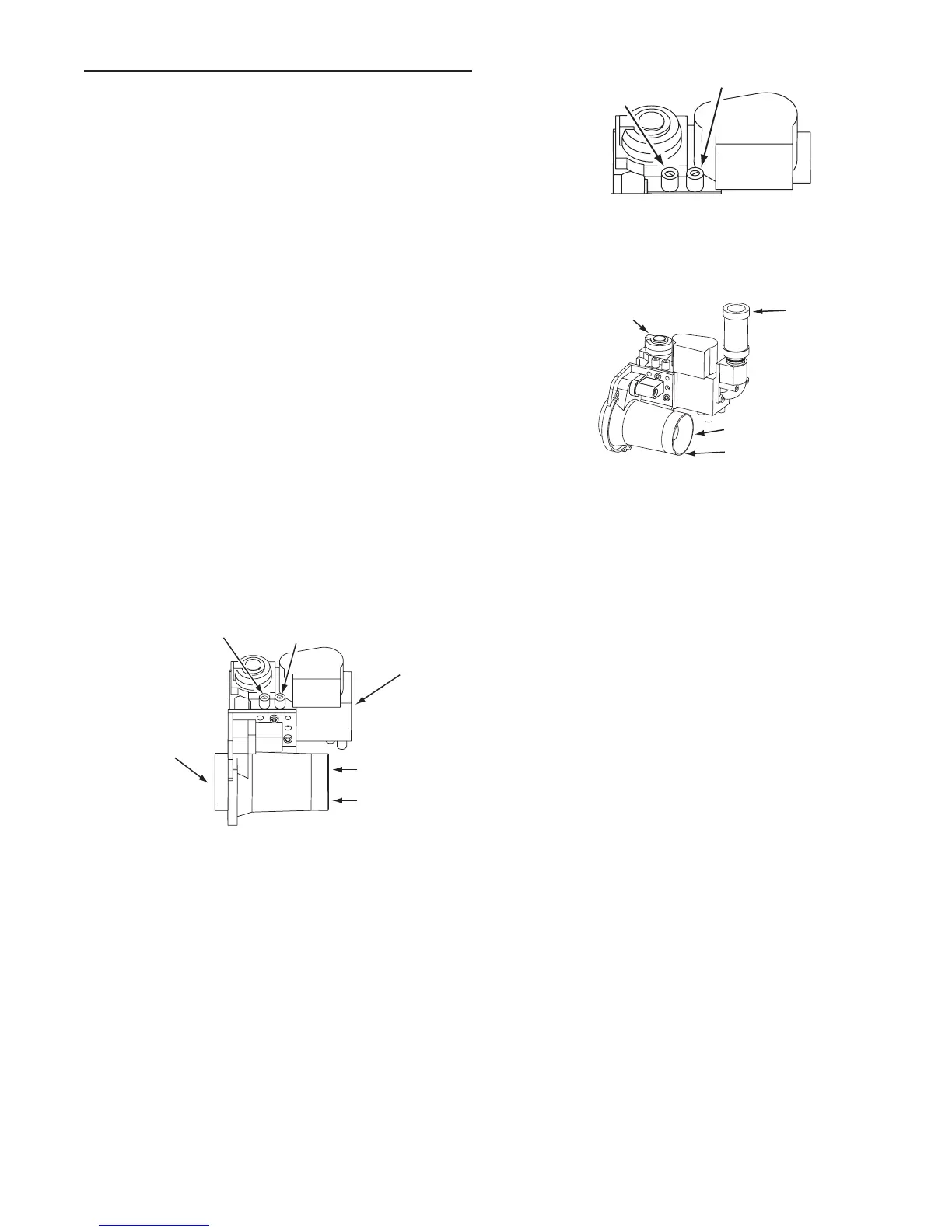
5. Connect the manometer to the supply gas pressure port on the
gas control valve, see Figure 41 and Figure 42.
On the water heaters covered by this manual there are test
ports for supply and manifold gas pressure readings on the gas
control valve. Using a small at tip pocket screw driver - open
the needle valve inside the supply gas pressure test port one
full turn only; turn the needle valve screw counter-clockwise to
open the valve. Slide the manometer sensing tube over the top
of the test port, see Figure 41 and Figure 42.
6. Open the Main Gas Shutoff Valve.
7. Measure and record the supply gas pressure, this is a “static”
supply gas pressure reading; while the water heater is not
ring. Adjust supply gas pressure as necessary, see Gas
Supply Systems on Page 17.
MANIFOLD GAS
PRESSURE
TEST PORT
(Non-Adjustable)
SUPPLY GAS
PRESSURE
TEST PORT
GAS CONTROL VALVE / VENTURI ASSEMBLY TOP VIEW
VENTURI
COMBUSTION
AIR INLET
GAS CONTROL
VALVE
COMBUSTION
BLOWER
CONNECTION
Figure 41
MANIFOLD GAS
PRESSURE
TEST PORT
(Non-Adjustable)
SUPPLY GAS
PRESSURE TEST PORT
GAS CONTROL VALVE TOP DETAIL VIEW
Figure 42
GAS CONTROL VALVE / VENTURI ASSEMBLY SIDE VIEW
VENTURI
SUPPLY GAS
CONNECTION
GAS
VALVE
COMBUSTION
AIR INLET
Figure 43
 Loading...