EasyManua.ls Logo

Polaris PGC User Manual

Polaris PGC
63 pages
To Next Page IconTo Next Page
To Previous Page IconTo Previous Page
Page #53 background image
53
Never use this water heater unless it is completely lled with water.
To prevent damage to the tank, the tank must be lled with water.
Water must ow from the hot water faucet before turning “ON” gas
to the water heater.
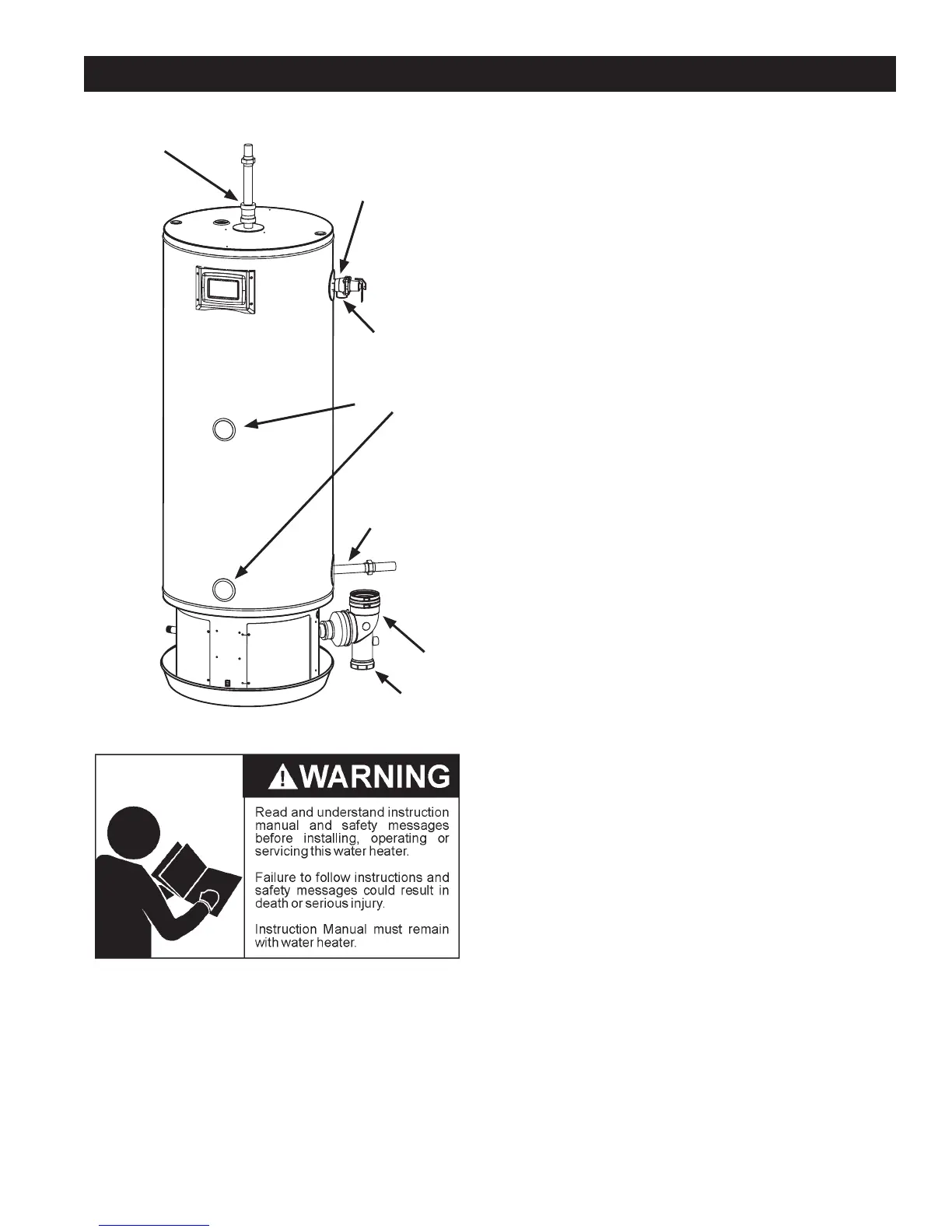
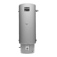
A *Condensation may be seen on the hot water outlet pipe in humid
weather or the hot water outlet connection may be leaking.
B. *Condensation may be seen on the cold water inlet pipe in humid
weather or the cold water inlet connection may be leaking.
C. Small amounts of water from temperature-pressure relief valve
may be due to thermal expansion or high water pressure in your
area.
D. *The temperature-pressure relief valve may be leaking at the tank
tting.
E. Water from a drain valve may be due to the valve being slightly
opened. (Not shown in Figure 46).
F. *The drain valve may be leaking at the tank tting. (Not shown in
Figure 46).
G. Leakage from recirculation plug or pipe connection. (Not shown in
Figure 46).
H. Leakage from the temperature probe connections.
I. Condensate from the exhaust connection.
J. Condensate Clean Out Cap
Leakage from other water heaters, water lines, or ground seepage
should also be checked.
* To check where threaded portion enters tank, insert cotton swab
between jacket opening and tting. If cotton is wet, follow the
“Draining” instructions in Draining and Flushing on Page 55 and
then remove the tting. Put pipe dope or teon tape on the threads
and replace. Then follow the instructions in Filling the Water Heater
on Page 44..
Figure 46
A: Hot Water Outlet
B: Cold Water Inlet
H: Temperature
Probe Connections
C: T & P
Connection
D: T & P Outlet
I: Flue Outlet
J: Condensate Clean
Out Cap
LEAKAGE CHECKPOINTS

Table of Contents

Questions and Answers:

Polaris PGC Specifications

General IconGeneral
BrandPolaris
ModelPGC
CategoryWater Heater
LanguageEnglish

Summary

COMMERCIAL GAS WATER HEATERS

POLARIS - POWER DIRECT VENT GAS MODELS WITH DIRECT SPARK IGNITION

Identifies the product line and key features.

MODELS PGC/SPC/BSS/BTS Series 200, 201 NATURAL GAS & PROPANE

Lists specific model series and fuel types.

SAFE INSTALLATION, USE AND SERVICE

SAFETY ALERT SYMBOLS

Explains hazard symbols (Danger, Warning, Caution).

GENERAL SAFETY INFORMATION

PRECAUTIONS

Lists general safety precautions to follow before operation.

GROUNDING INSTRUCTIONS

Details requirements for proper electrical grounding.

GENERAL SAFETY INFORMATION

WARNING Breathing Hazard - Carbon Monoxide Gas

Highlights the dangers of carbon monoxide gas.

DANGER Flammable Vapors

Warns about explosion hazards from flammable vapors.

GENERAL SAFETY INFORMATION

WARNING Electrical Shock Hazard

Warns about electrical shock hazards.

WARNING Fire and Explosion Hazard

Specific fire and explosion warnings.

INSTALLATION REQUIREMENTS FOR THE COMMONWEALTH OF MASSACHUSETTS

INSTALLATION OF CARBON MONOXIDE DETECTORS

Requirements for CO detector installation.

INTRODUCTION

QUALIFIED INSTALLER OR SERVICE AGENCY

Defines requirements for qualified personnel.

DIMENSIONS AND CAPACITY DATA

ROUGH IN DIMENSIONS: ALL MODELS

Provides detailed rough-in dimensions for all models.

DIMENSIONS AND CAPACITY DATA

TABLE 2 - CAPACITY, GAS AND ELECTRICAL CHARACTERISTICS

Details capacity, gas type, and electrical specifications.

FEATURES AND COMPONENTS

34 GALLON UNIT

Identifies components of the 34-gallon model.

FEATURES AND COMPONENTS (CONT.)

50 GALLON UNIT

Identifies components of the 50-gallon model.

FEATURES AND COMPONENTS (CONT.)

LIST OF COMPONENTS

Provides a numbered list of all components.

CONTROLS AND SWITCHES

BLOCKED INTAKE SWITCH

Describes the blocked intake pressure switch.

INSTALLATION CONSIDERATIONS

LOCATING THE WATER HEATER

Provides guidance on choosing a suitable location.

DANGER Flammable Vapors

Warns about flammable vapors in installation location.

INSTALLATION CONSIDERATIONS (CONT.)

COMBUSTION AIR AND VENTILATION

Explains requirements for combustion air.

CORROSION AND WATER QUALITY

Discusses water quality impact on the heater.

INSTALLATION REQUIREMENTS

GAS SUPPLY SYSTEMS

Details requirements for gas supply systems.

POWER SUPPLY

Specifies power supply requirements.

INSTALLATION REQUIREMENTS (CONT.)

MIXING VALVES

Instructions for installing mixing valves.

CIRCULATION PUMPS

Information on using circulation pumps.

INSTALLATION REQUIREMENTS (CONT.)

SPACE HEATING AND POTABLE WATER SYSTEM

Guidelines for combined heating and potable water systems.

THERMAL EXPANSION

Explains thermal expansion and its control.

INSTALLATION REQUIREMENTS (CONT.)

TEMPERATURE-PRESSURE RELIEF VALVE

Details about the T&P relief valve.

T&P VALVE DISCHARGE PIPE REQUIREMENTS

Specifies requirements for the T&P discharge pipe.

INSTALLATION REQUIREMENTS (CONT.)

CONDENSATE DRAIN INSTALLATION

Instructions for installing the condensate drain.

VENTING INSTALLATION

VENT INSTALLATION CONSIDERATIONS

Key factors to consider during vent installation.

VENTING INSTALLATION (CONT.)

VENT PIPE TERMINATION

Details on vent pipe termination types and locations.

PLANNING THE VENT SYSTEM

Guidance on planning the vent system layout.

VENTING INSTALLATION (CONT.)

TABLE 7A. Elevations up to 2000 Ft.

Maximum vent pipe lengths for lower elevations.

INTEGRATED FILTER INSTALLATION

Instructions for installing the air intake filter.

VENTING INSTALLATION (CONT.)

DIRECT VENT AIR INTAKE MOISTURE PROTECTION

How to protect the air intake from moisture.

HORIZONTAL VENT TERMINAL INSTALLATION

Steps for installing horizontal vent terminals.

VENTING INSTALLATION (CONT.)

VERTICAL VENT TERMINAL INSTALLATION

Steps for installing vertical vent terminals.

PITCHED ROOF INSTALLATION (ALL MODELS)

Requirements for pitched roof vent termination.

TERMINATION CLEARANCES SIDEWALL DIRECT VENT

DIRECT VENT (using outdoor air for combustion)

Overview of direct vent configurations.

DIRECT VENT INSTALLATION DIAGRAMS

SIDEWALL VENT INSTALLATION (ALL MODELS)

Diagram for sidewall vent installation.

CONCENTRIC VENT INSTALLATION

SAFETY CONSIDERATIONS

Safety precautions for concentric venting.

VENTING MULTIPLE UNITS

CONCENTRIC VENTING MULTIPLE WATER HEATERS (ALL MODELS)

Concentric venting for multiple units.

WATER HEATER INSTALLATION

CONDENSATE DRAIN INSTALLATION

Steps for installing the condensate drain.

SUPPLY GAS LINE INSTALLATION

Guidelines for installing the gas supply line.

WATER HEATER INSTALLATION (CONT.)

GAS LINE LEAK TESTING

Procedure for leak testing gas connections.

ELECTRICAL WIRING

ENABLE/DISABLE CIRCUIT (For Building Management Systems)

How to use the enable/disable circuit for BMS.

WATER LINE CONNECTIONS

Requirements for water line connections.

ELECTRICAL WIRING (CONT.)

T&P VALVE DISCHARGE PIPE

Specifics on T&P valve discharge pipe.

TEMPERATURE REGULATION

HIGH TEMPERATURE LIMIT CONTROL (ECO)

Explanation of the ECO switch.

THERMOSTAT CONTROL

How to control the thermostat settings.

CONTROL SYSTEM OPERATION

CONTROL SYSTEM NAVIGATION

How to navigate the control system menus.

THE DESKTOP SCREEN

Description of the default screen display.

CONTROL SYSTEM OPERATION (CONT.)

STATUS ICONS

Explains the meaning of status icons.

CONTROL SYSTEM OPERATION (CONT.)

OPERATING STATES

Lists and describes common operating states.

CONTROL SYSTEM MENUS

Overview of available control system menus.

USER SETTINGS & CONTROL SYSTEM MENUS

OPERATING SET POINT AND DIFFERENTIAL ADJUSTMENT

How to adjust operating set point and differential.

USER SETTINGS & CONTROL SYSTEM MENUS (CONT.)

HEATER STATUS MENU

Menu to check the status of heater components.

USER SETTINGS & CONTROL SYSTEM MENUS (CONT.)

DISPLAY SETTINGS

Options for adjusting display settings.

HEATER INFORMATION

Displays operational history and component versions.

USER SETTINGS & CONTROL SYSTEM MENUS (CONT.)

CURRENT FAULT

Displays active fault messages.

FAULT HISTORY

Lists past fault and alert messages.

USER SETTINGS & CONTROL SYSTEM MENUS (CONT.)

SERVICE CONTACT INFORMATION

Access to enter service contact details.

START UP

FILLING THE WATER HEATER

Instructions for filling the water heater tank.

START UP (CONT.)

INITIAL START UP

Step-by-step guide for initial start-up.

REQUIRED TEST EQUIPMENT

Lists necessary equipment for testing.

LIGHTING THE WATER HEATER

FOR YOUR SAFETY READ BEFORE LIGHTING

Critical safety warnings before lighting the unit.

OPERATING INSTRUCTIONS

Steps for operating the water heater.

LIGHTING THE WATER HEATER (CONT.)

CHECKING THE FIRING RATE

How to check the actual firing rate.

HIGH ALTITUDE INSTALLATIONS

Considerations for high altitude installations.

TROUBLESHOOTING

INSTALLATION CHECKLIST

Checklist for common installation errors.

SEQUENCE OF OPERATION

Detailed explanation of the operational sequence.

TROUBLESHOOTING (CONT.)

SEQUENCE OF OPERATION FLOW CHART

Visual flow chart of the sequence of operation.

OPERATIONAL PROBLEMS

NOT ENOUGH OR NO HOT WATER

Common causes for lack of hot water.

WATER IS TOO HOT

Troubleshooting excessively hot water.

OPERATIONAL PROBLEMS (CONT.)

FAULT AND ALERT CONDITIONS

Understanding fault and alert messages.

FAULT AND ALERT MESSAGES

List of displayed fault/alert messages.

FAULT AND ALERT MESSAGES (CONT)

POSSIBLE CAUSES - CHECK/REPAIR

Potential causes and checks for faults.

LEAKAGE CHECKPOINTS

PERIODIC MAINTENANCE

VENTING SYSTEM INSPECTION

How to inspect the venting system.

TEMPERATURE-PRESSURE RELIEF VALVE TEST

Procedure for testing the T&P relief valve.

PERIODIC MAINTENANCE (CONT.)

DRAINING AND FLUSHING

Instructions for draining and flushing the tank.

DIAGRAMS

CCB - CENTRAL CONTROL BOARD LAYOUT

Diagram of the central control board layout.

WIRING DIAGRAM

CIRCULATION PUMP WIRING DIAGRAMS

PIPING DIAGRAMS

FIGURE 53: SAMPLE MIXING VALVE INSTALLATION (All Models)

Diagram showing mixing valve installation.

PIPING DIAGRAMS (CONT.)

FIGURE 54: AIR HANDLER PIPING INSTALLATION (All Models)

Diagram for air handler piping installation.

NOTES

POLARIS

Related product manuals