ELECTRICAL
10.4
COOLANT TEMPERATURE
SENSOR TEST (HOT
LIGHT)
With the ignition switch (and engine stop switch) “ON”,
power is delivered to the hot light via the Red/White
wire. The Blue/White wire (ground) out of the light
socket is connected to the coolant temperature
sensor on the cylinder head. In normal operating
conditions, the temperature sensor is non-conductive
(open). If engine coolant reaches the specified
temperature, the sensor becomes conductive
completing the ground path for the light.
With engine cold, disconnect lead and measure
resistance of sensor between connector terminal and
ground. There should be no continuity or very high
resistance (megohms).
Hot Light On
221° F (105° C)
FAN CONTROL CIRCUIT
OPERATION /
TESTING
The fan switch is located on the radiator. Power is
supplied to the fan switch via the Red/Black wire when
the ignition key is ON. When the fan switch reaches
the specified temperature, it becomes conductive and
sends power to the fan motor through to the
Orange/Black wire. The ground path for the fan motor
is through the Brown harness wire.
CAUTION: Keep hands away from fan blades
during this procedure. Serious personal injury
could result.
NOTE: The fan switch may not function or operation
may be delayed if coolant level is low or if air is trapped
in the cooling system. Be sure cooling system is full and
purged of air. Refer to Maintenance Chapter 2 for
cooling system information.
FAN CONTROL SWITCH
BYPASS
TEST
1. Disconnect harness from fan switch on radiator.
2. Place a jumper wire between the Red/Blk and
Org/Blk wires in the connector.
3. With the parking brake on, turn the ignition key
(and engine stop switch) “ON”. The fan should
start running.
4. If the fan runs with the jumper wire installed,
check the fan control switch and connector
terminals. If the fan does not run or runs slowly
with the jumper wire installed, check the fan motor
wiring, ground, and motor condition (refer to Fan
Motor Testing this section). Repair or replace as
necessary.
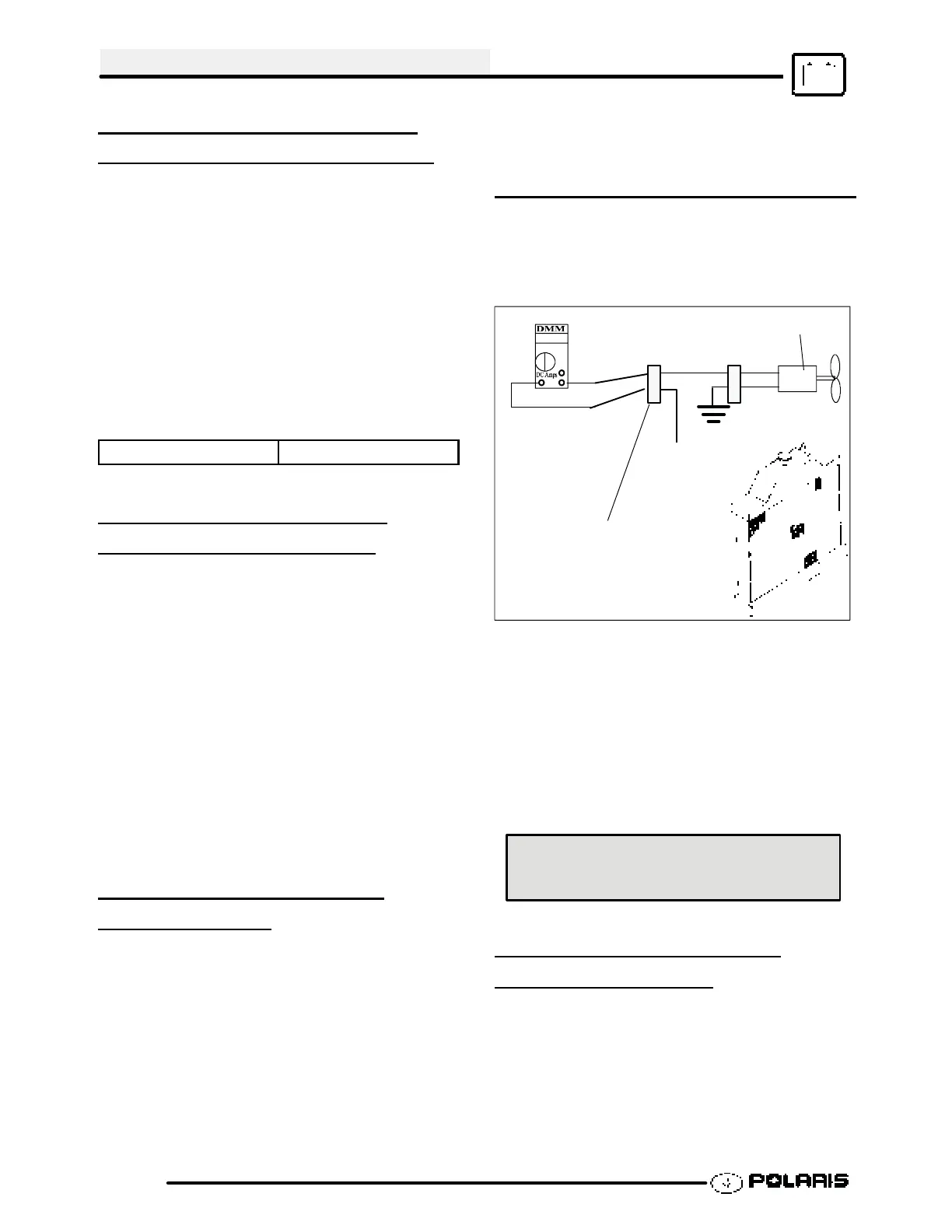
FAN MOTOR CURRENT DRAW
A current draw test will provide a good indication of fan
motor condition. A worn or damaged fan motor will
draw more current, which causes a reduction in blade
speed and reduced cooling.
Fan Motor
Red/Blk
Connect ammeter
to R/B and Or/Blk
Or/Blk
Fan
Switch
Harness
Or/Blk
Brn
1. Disconnect the harness from the fan switch.
2. Connect a DC ammeter in between the fan switch
harness wires as shown.
3. Be sure fan blade is free to rotate.
4. Turn ignition key and engine stop switch to “ON”
position. Read the current draw on ammeter with
fan running.
5. If the fan motor draws more than 6.5 Amps,
replace the motor.
Fan Motor Current Draw:
Should Be Less Than 6.5 Amps
FAN CONTROL SWITCH
OPERATION
TEST
1. Place switch in a water bath and submerse it to
the base of the threads. Do not allow threads to
contact container or inaccurate reading will result.
2. Heat the coolant slowly and monitor the
temperature with a thermometer or Fluket meter
pyrometer. The switch should be closed
(conductive) at the “ON” temperature indicated in
 Loading...