3
List of Illustrations
Figure Page
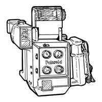
1-1 Camera Features and Controls ............................................................. 4
1-2 Camera Outline Dimensions.................................................................. 6
2-1 Aperture Size Determination (f\stop) ..................................................... 7
2-2 Light Interception (A) and Shutter Blade (B) Positions .......................... 8
2-3 Rotation of Light Interception Blade ...................................................... 9
2-4 Shutter Blade Unlatching Action............................................................ 10
2-5 Wheel Cam Closure of X-sync Contacts ............................................... 10
2-6 Optical Path/Four-Frame Exposure ....................................................... 11
3-1 Removing Lens, Tape Measure, Aperture and Shutter.......................... 13
3-2 Removing Camera Back ........................................................................ 14
3-3 Removing Backplate and Handstrap ..................................................... 14
3-4 Removing Viewfinder Object Frame ...................................................... 16
3-5 Removing Viewfinder Cover and Lens................................................... 17
3-6 Flash Hot Shoe Disassembly................................................................. 18
3-7 Shutter Release Button Disassembly .................................................... 19
3-8 Accessing Aperture Mechanism ............................................................ 20
3-9 Accessing Aperture Blades.................................................................... 20
3-10 Aperture Mechanism Blade-Actuating Parts.......................................... 22
3-11 Removing Aperture and Shutter Mechanism ......................................... 23
3-12 Shutter Board Sub-Assembly................................................................. 24
3-13 Shutter Blade Positions ......................................................................... 25
3-14 Release Slide Assembly ........................................................................ 26
3-15 Synchro (X) Switch ................................................................................ 26
3-16 Microswitch ............................................................................................ 27
3-17 Shutter Drive: Release Lever, Pressure Lever and Wheel Assembly ... 28
3-18 Synchro (X) Switch Contact Adjustment ................................................ 29
3-19 Flash Circuit Wiring Diagram ................................................................ 30
3-20 Flash Circuit Schematic......................................................................... 30
 Loading...