)LUVW6WHSV
&RQWURO(OHPHQWVRIWKH9LEURPHWHU
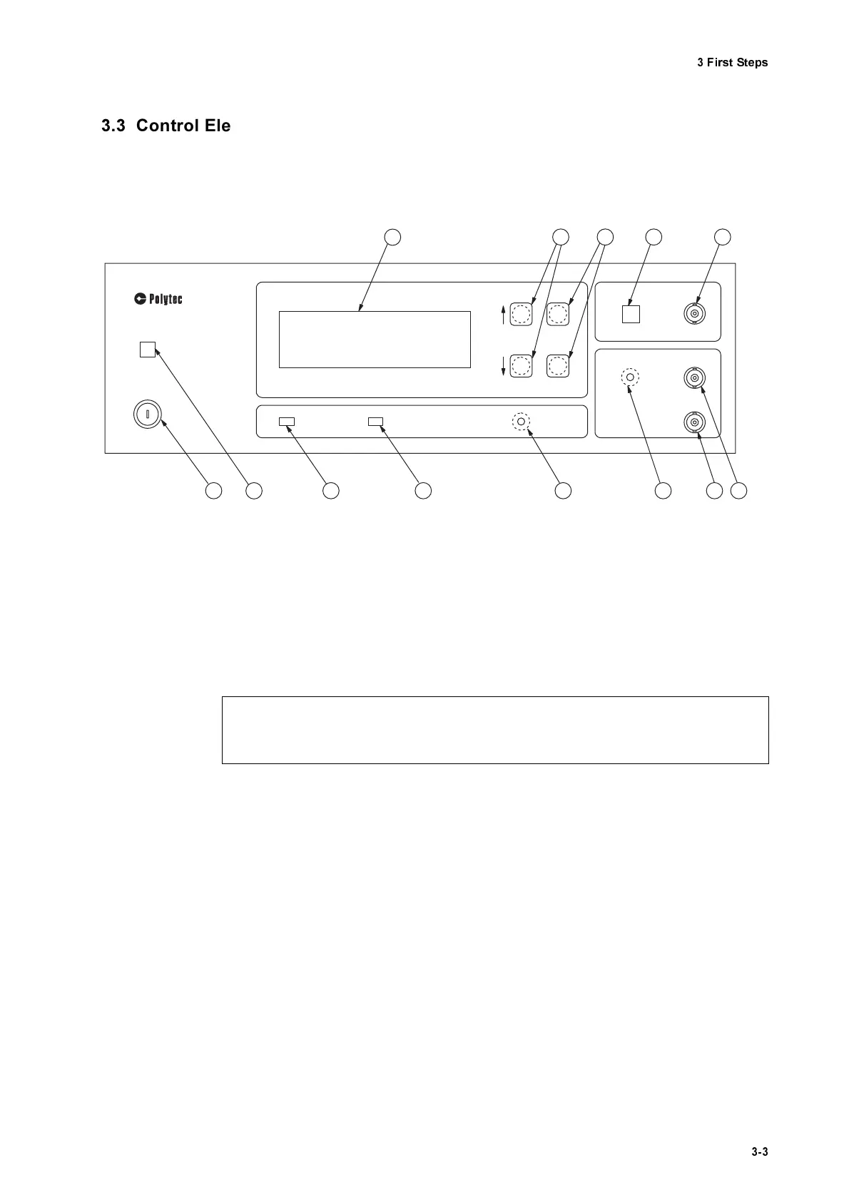
&RQWUROOHU
The front panel of the controller is shown in figure 3.1.
32:(5
- L
ED
The L
ED
lights up when the key switch on the controller is turned to posi-
tion I and indicates that the controller is ready to operate.
0DLQV6ZL W FK
This key switch disconnects the vibrometer from the mains (position O)
and is used to switch it off in the case of danger.
/LTXL G& U\VWDO' LVSO D\/&'
with background lighting
This display shows the configuration and the settings of the vibrometer.
The organization of the display and how to use it to operate the vibrome-
ter are described in detail in section 5.9.
)81&7,21
- keys
Using these keys the cursor is moved vertically up (
↑)
or down (
↓
) on the
display. This is used to select parameters or to change between menus
(refer to section 5.9.1).
6(77,1 *
- keys
Using these keys the settings are changed to higher (+) or lower (-) values
(refer to section 5.9.1).
Figure 3.1: Front view of the controller
O
POW ER
O FV 3001
VIBRO M ETER CO NTRO LLER
3
2 13 12 11 10
LLO
REM OTE
RESET
FUNCTION
SETTING
4 5 6 7
+
-
OVER
OUTPUT
VELO CITY
DISPLACEM ENT
CLEAR
OUTPUT
9 8
I
1
&DXWLR Q
$OZD\V connect the connecting cable to the sensor head EHIRUH switching the controller
on!