0DNLQ J0HDVXUHPHQWV
2SWLPL]LQJWKH
5)EDQGZLGWK
The input of the vibrometer is equipped with an RF band-pass filter (refer to
section D.2). To achieve optimal adaptation to the FM-signal bandwidth, the
RF bandwidth is automatically adjusted according to the velocity measure-
ment range set. As this process also affects the input signal of the displace-
ment decoder, the setting of the velocity measurement range is relevant, even
if only the displacement output is being used.
The signal-to-noise ratio of the displacement measurement can be improved
with targeted limitation of the RF bandwidth which is particularly important in
the case of weak optical signals. This means that the velocity measurement
range should be selected to be as low as the application allows. The maxi-
mum velocity must not exceed the respective full scale range i.e. 10 times the
scaling factor (e.g. 50mm/s for the measurement range 5 ). If the L
ED
VELOCITY OVER lights up continuously or the displacement signal breaks
down, the next highest velocity measurement range has to be selected.
If however the optical signal is constantly good, the range 1,000 should
be selected as it does not limit the bandwidth and therefore its influence does
not need to be taken into consideration.
8VLQJWKH
&/($ 5
IXQFWLRQ
As there is no lower frequency limit for the displacement decoder, it can also
measure stationary signals (DC). After setting a certain displacement mea-
surement range, a certain voltage is present at the output (the so-called DC
offset) which depends on the distance of the object to the sensor head and on
the thermal drift of the interferometer. Dynamic displacements of the object
(AC) are correctly added to or subtracted from this DC offset as long as the
output voltage does not exceed
±
8V. Otherwise the output voltage will jump
from the positive end of range to the negative and vice versa as the internal
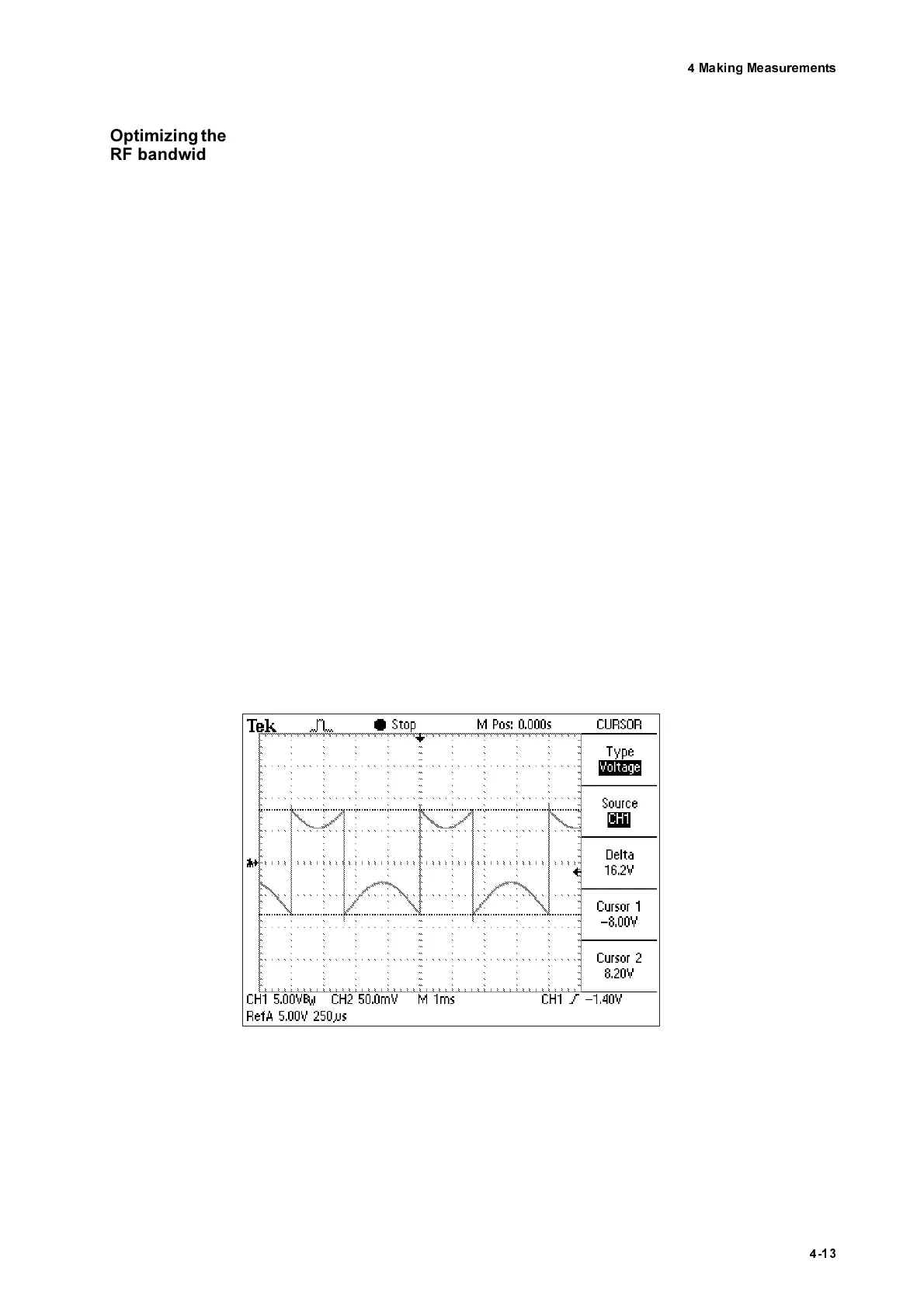
counter overflows (refer to section D.5.3), and as a result the AC signal is dis-
torted. This is shown as an example in the oscilloscope trace in figure 4.7.
Before making a measurement, the DC offset should therefore be reset to
zero to make use of the full displacement measurement range. This can be
done by pressing the CLEAR key on the front of the controller or by feeding
an electrical pulse to the corresponding BNC jack. The latter is particularly
advantageous in the case of periodic signals with a superimposed translation.
In such cases the counter quickly overflows due to the DC signal of the trans-
mm
s
----------
V
mm
s
----------
V
Figure 4.7: Displacement signal when the counter overflows due a DC offset