Automatic boiler for pellets – User manual
29
8.2 CONTROL UNIT
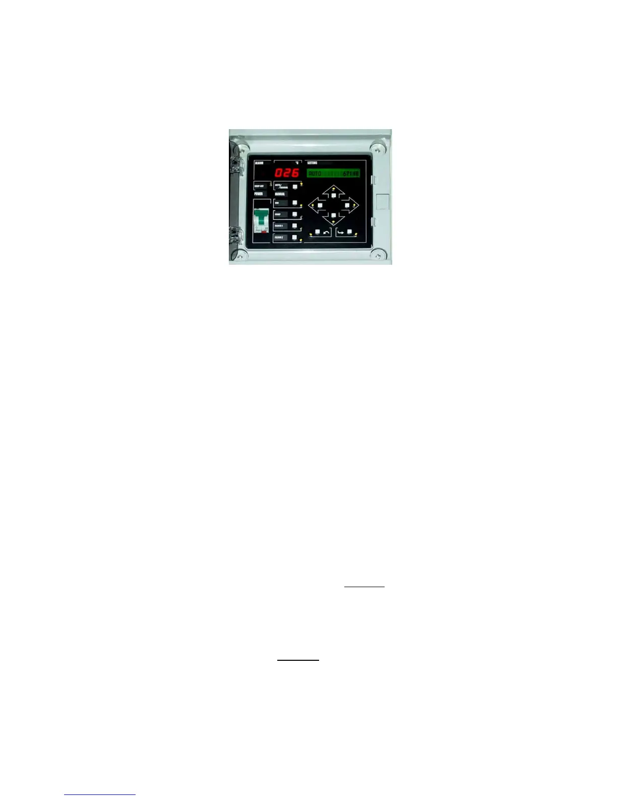
A universal control unit type RKP 12157 is used for all boilers of the KP 10-20-50-11-21-51 series.
Figure number 4 - Control unit of the boiler – RKP 12157
The control unit serves for automatic control of the boiler operation via regulation elements (thermometers,
sensors) in AUTO, MOD and SW Tank operating modes and in supporting modes - START, STAND BY,
CHIMNEYER.
It also enables MANUAL control MODE of the inbuilt elements, which is used, apart from other things, when
putting the boiler into operation.
The control unit is drafted as a compact aggregate.
Circuits of the control unit are protected by a tube fuse T100L.
The control unit is equipped with a button cell to back up time data in case of power failure.
SEE MORE INFORMATION IN CHAPTERS 5.1 and 8.2.
8.3. BURNER INCLUDING THE F2 FEEDER
The burner furnace is schematically displayed as a part of figure number 1 and it consists of the following parts:-
the burner body including the inbuilt fuel route, extension parts for installation of the connecting hose, and
extension parts for the ventilator installation
- F2 feeder - a set of a screw and a motor with a transmission
- pulsed revolution sensor
- connecting hose made of non-flammable material
- ventilator (of the burning air)
- electric resistance coils of the automatic ignition (equipment according to the boiler type).
The burner body - (patent protected) is of a case type made of a highly alloyed material with an angled bottom
fuel intake. The fuel is conveyed to the burner grate by an inbuilt
feeder F2
, powered by an electric motor with a
transmission.
A set of slot nozzles in the burner grate ensures good intake of combustion air, so the combustion of the fuel
supplied to the combustion chamber of the burner is controlled and efficient. Burnt out fuel is then moved through
the combustion chamber overflow edge into the ash pan and/or blown out into the ash pan by the combustion air
circulation.
Inner area of the burner body is connected to a
ventilator
the output of which is controlled via adjustment in the
control unit.
Connecting hose (between F1 and F2 feeders) from non-flammable material connects both feeder and is a part
of the fuel conveying routes.


 To Next Page