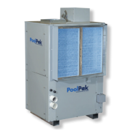
Do you have a question about the PoolPak AW 3500 and is the answer not in the manual?
Covers introduction, operating cost, application, moisture loads, effects of moisture, and indoor air quality.
Discusses occupant comfort factors and the importance of pool water chemistry.
Covers equipment choices, dehumidification methods, and airside design considerations.
Explains the core principles of the dehumidification system and its operation.
Details the ECC-PCP controller, its functions, and advanced features like humidity control.
Covers RoofPak system, PoolComPak selection, configurations, and typical applications.
Provides technical summaries, dimensions, and weights for various units.
Presents performance summary data for PoolComPak AW series units.
Presents performance summary data for PoolComPak HCD series units.
Details hot water coil capacities for vertical and horizontal models.
Covers refrigerant charge, remote condensers, and electric duct heaters.
Covers PCP installation, introduction, and unit/facility interface.
Covers unit handling, required clearances, and mounting procedures.
Details power supply requirements and control wiring connections.
Provides guidance on pool water piping and condensate drain requirements.
Provides comprehensive guidelines for field-installed refrigerant piping.
Instructions for charging refrigerant and oil, including sample calculations.
Shows wiring for auxiliary heaters, field wiring, and fire control systems.
Explains the RIU keypad, status display, and basic navigation.
Instructions for changing air, humidity, and pool temperature set points.
Explains network operation, configuration parameters, and unit roles.
Details accessing the service menu and configuring digital/analog inputs/outputs.
Details manual mode options and utilities for configuration and access.
Shows wiring for auxiliary heaters in multiple unit installations.
Provides a general field wiring diagram for the ECC-PCP system.
Details the connection diagram for integrating with a fire control system.
| Brand | PoolPak |
|---|---|
| Model | AW 3500 |
| Category | Dehumidifier |
| Language | English |


 Loading...