PoolPak PCP Series – Indoor OMM 28 September 2020
Outdoor Air Condensers and Fluid Coolers Layout and Components.
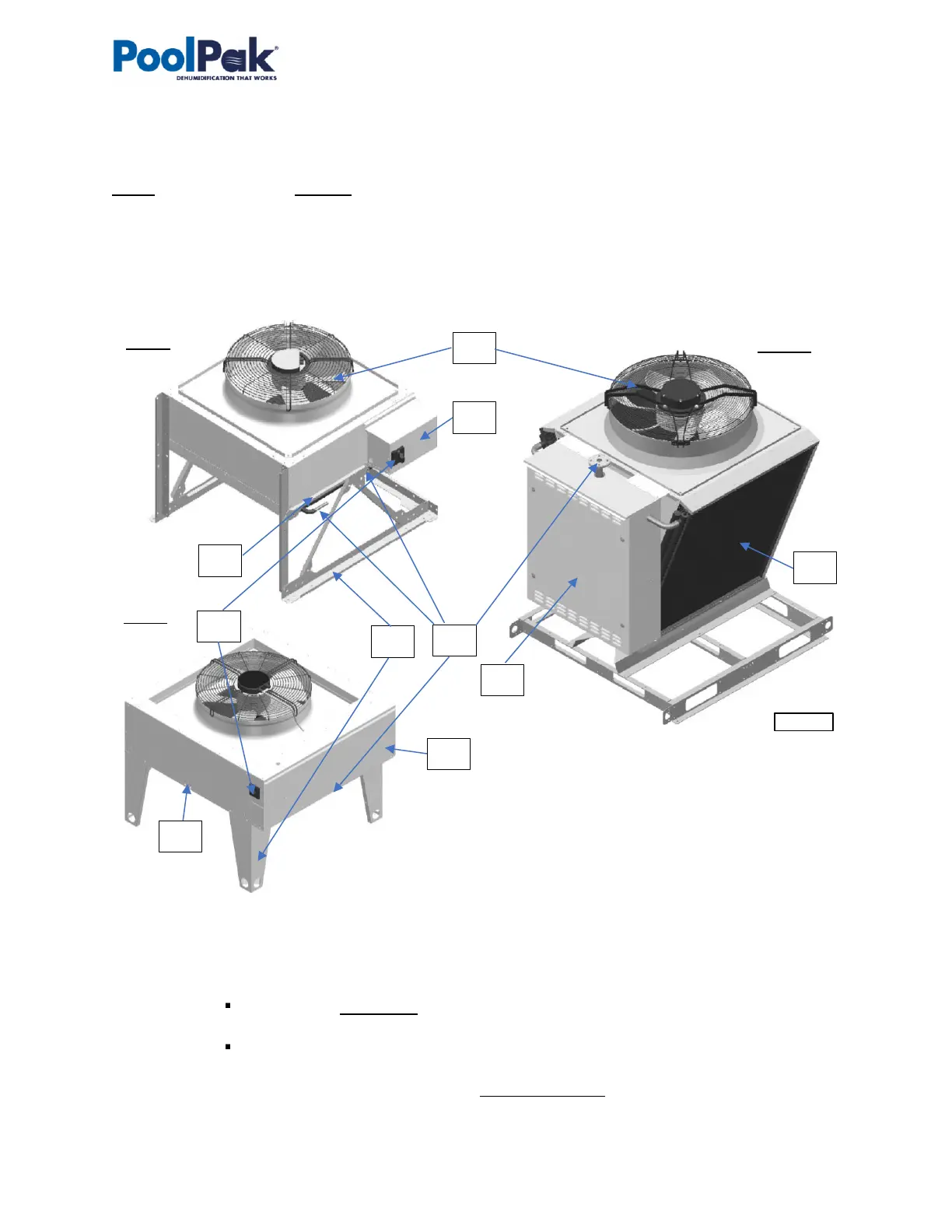
The general layout of AC options (air-and water-cooled) is shown on Pic.D.5 below with the outdoor air condenser
NC-Z-1 (left) and fluid cooler NG-V-11 (right) as an example. While layout and main components are similar for all
applicable AC options, there are some deviations (number of fans, coil sizes, composition, etc.). Refer to AC
Options Basic View (Basic Information) for additional information.
• Cooling (AC) coil(s) (31) (where heat from refrigerant in the outdoor condenser or glycol mixture in fluid cooler
is rejected to the ambient air) is mounted onto metal frame/air box upstream (before) the fan (32), that pulls
the air through the coil to absorb the heat.
o Condenser/cooler piping connections (33) are identified respectively (IN – OUT, Hot gas – Liquid etc.);
In some cases, fluid cooler piping connection(s) may be located within pump package box
(37), if fluid cooler is provided with one.
Piping connection location may vary – refer to particular cooler/condenser labels, stickers,
submittal and other documentation.
o Depending on the type, size and installation, outdoor condensers may be provided with different set
of legs/supports (34), which are required assembly on-site – refer to the Installation manual.
 Loading...