September 2020 31 PoolPak PCP Series – Indoor OMM
Compressor Circuit Operation
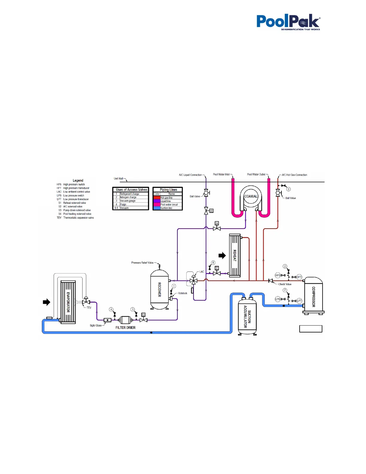
Piping schematic for compressor circuit is shown on Pic. E.1.
When a demand requires the compressor to operate, the following sequence occurs:
• Once blower operation, related safeties and timers are confirmed by the control system, the pump down
solenoid valve opens and once pressure stabilizes, the compressor starts.
• Based on the premise air temperature, the refrigeration reheat and/or AC solenoid valve opens, allowing
refrigerant to flow through the respective condenser:
o if more heat is required by the room air, the reheat solenoid valve opens (heat is rejected to the
premise); if more cooling is required by the room air, the AC solenoid valve opens (heat is rejected
outdoors (via outdoor condenser or plate heat exchanger).
o Outdoor condenser or fluid cooler fan is engaged only if hot gas is diverted outdoors and compressor
pressure is higher than pre-set level (see Outdoor Condenser and Fluid Cooler Operation below).
• Dehumidifiers, equipped with pool water heating option, also engage the refrigeration pool water heating
solenoid valve to reject heat into the pool water, based on pool water temperature.
• Once demand for the compressor’s operation is removed (respective call is satisfied), the pump down solenoid
valve closes; once the compressor suction pressure reaches the pre-set pressure, the compressor stops.
Note. Suction accumulator is not typically found on 2-7 ton models.
Outdoor Air Condenser and Fluid Cooler Operation.
Based on the type of the outdoor condenser or fluid cooler fans’ type (two-speed fans or EC-type/modulating
fans), respective signal(s) are sent by control system to engage said fan(s): for two-speed fans - on/off signals
(switching speeds, based on compressor head pressure level), for EC-type fans - variable 0-10VDC signal
(proportional to the compressor head pressure level). Refer to the fans’ type and wiring diagram if/when needed.
If the fluid cooler is equipped with the built-in pump package (to establish cooling fluid flow between dehumidifier
and the fluid cooler or to serve as additional/booster pump), the said pump is also engaged along with fluid cooler
fans – pump would stay engaged while fans are engaged (regardless of the fans’ speed).