4
2. SYSTEM OVERVIEW
The chlorinator’s cell must be installed on the return circuit downstream from the lter and any
heating systems (particularly electric heater)
A « by-pass » installation is recommended so that it is easier to work on the chlorinator and for
wintering purposes.
The electrolysis cell can be positioned anywhere but it is preferable to use a conguration that
facilitates the evacuation of air bubbles. The accessories’ stand must be installed upstream
from the cell.
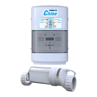
There are three main components to your Chlorinator system: the Control Module, the
Electrolytic Cell, and the Flow Switch.
Control Module: This component supplies power to the cell and allows you customize the
system's operation, in order to meet your pool's unique needs.
Electrolytic Cell: This component creates chlorine as the water inside passes through and
returns to the pool. The Electrolytic Cell ("Cell") contains a set of titanium plates that use a
low level of electrical power to generate chlorine from salt in the water. The Cell comes with
Unions to connect to the plumbing; each Union has a Threaded Collar that secures the Cell to
the Unions, and enables the Cell to be easily removed for cleaning and inspection purposes.
Flow Switch: This component ensures that there is adequate water ow for the Cell to
activate.
List of equipements
supplied
• 1 complete electrolysis cell
• 1 electric control unit
• 1 cell power supply cable
• 2 short 63/50 reducers
• 1 paddle-operated ow
switch
• 1 wall mounting kit
• 1 installation and user’s
manual