6
4. INSTALLATION
From the supplied components, select the plumbing ttings that match the existing pool
plumbing
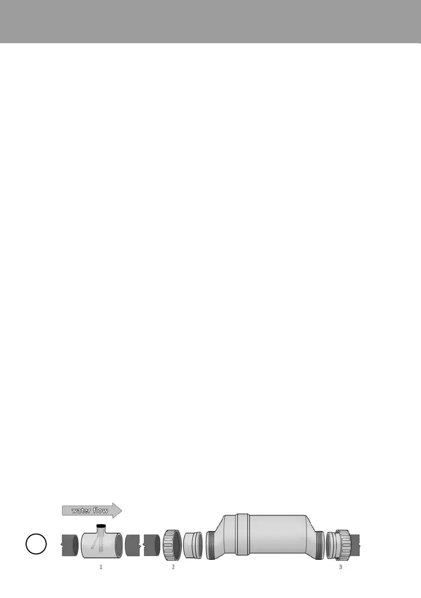
For proper plumbing, refer to the overview diagram on page 4. NOTE: The following
are basic plumbing instructions for the typical installation (Conguration #1), which
entail positioning the Flow Switch and Cell adjacent to each other on 2" plumbing. Your
installation may vary depending on space available and your specic arrangement of
equipment. IMPORTANT: Ensure that the pool pump and all AC power is turned o
before installation.
TIP: Conrm installation layout rst!
The Flow Switch and Cell are to be tted into the return line as the last pieces of
equipment the water passes through before returning to the pool: always after the
pump, lter, heater (if applicable), etc. If a heater is present, all equipment must be a
minimum distance away, per heater manufacturer recommendations.
Lay out your equipment to ensure there is enough pipe space available.
• When positioning the Flow Switch, ensure at least 6 to 12” (30cm) of straight pipe
before the Flow Switch. If installed after the Electrolytic Cell, the Cell provides this
space. The raised arrow on the black plastic cap must be pointed with the direction of
water ow as it returns to the pool. If installed horizontally, ensure that the wire-side
faces upwards. The Flow Switch is approximately 4» in length; the typical gap required
is 1 ¼’’ (400mm).
• When positioning the Cell, you can consider the side of the cell with the cord the
«inlet» side. If installed horizontally, ensure that the wire- side faces upwards. From
end to end, the Cell with both Unions is approximately 15 ¾’’ (38mm) in length; the
typical gap required is 13 ¼’’ (33mm).
Refer to the overview diagram on page 3 for alternate congurations. For combined
pool and spa systems with a spillover, congurations #2 or #3 allow chlorination for
both the pool and spa during spillover but preventing possible over-chlorination when
operating the spa only. Vertical Installation Kits are also available to minimize plumbing
space required and increase ease of installation.
TIP: Double-check that all Cell and Flow Switch cables can reach the Control Panel.
NOTE: For installations with 1 ½’’ (38mm) plumbing, use 2’’ to 1 ½’’ reducer bushings
with ow switch, and use alternate 1 ½’’ Cell Unions; be sure to note any new or
additional measurements before cutting pipe
ø50mm