7
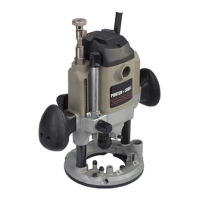
4. Insert the templet guide (A) Fig. 3, through the
templet guide insert (B), and secure with a locknut
(C). NOTE: Insert the templet guide through the
side of the templet guide insert that has a
recessed area (D) Fig. 3.
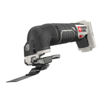
5. Turn the router upside down and stand it on
the motor cap (Fig. 4).
6. Insert the templet guide insert into the center
of the sub-base (Fig. 4).
7. Install the three screws provided (slotted
screwdriver or T20 torx wrench) and tighten until they stop, then back out
1
/
2
turn.
8. Push the base down until the templet guide centers itself on the collet nut
(D) Fig. 8, and hold in this position (Fig. 4A).
9. Move the plunge locking lever (C) Fig. 8 to the lock position.
10. Tighten the three screws securely.
11. Push down on the base and move the plunge locking lever (C) Fig. 8
back to the free motion position.
12. Allow the base to slowly move up until it stops (Fig. 4).
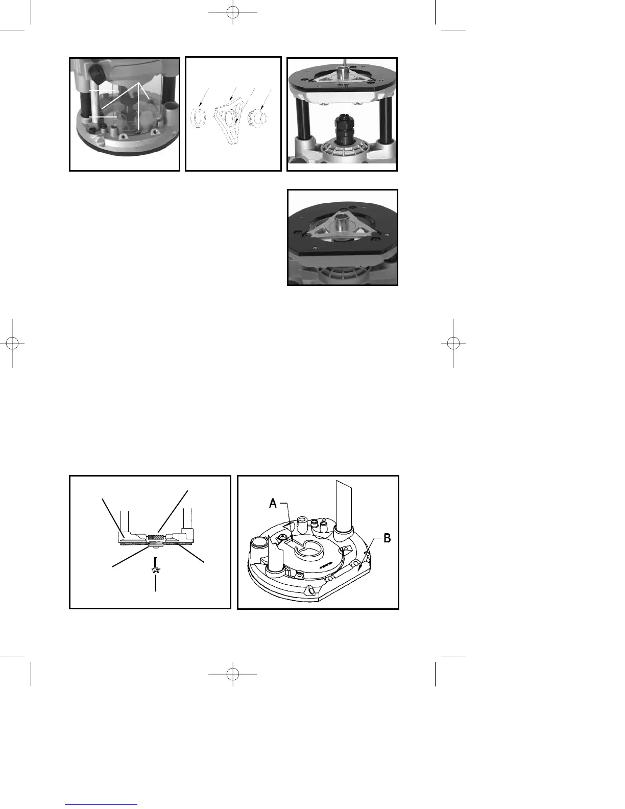
13. Reinstall clear dust cover and chip deflector.
NOTE: To ensure the proper dust collection operation, install the
dust cover with the slot (A) Fig. 6 in top of dust cover. Position it
opposite the flat side (B) Fig. 6 on the base.
NOTE: See Fig. 5 for proper orientation of templet guides.
Fig. 2
Fig. 3 Fig. 4
C
BD
A
Fig. 4A
A
B
C
Fig. 5
LOCKNUT
ROUTER
BASE
SUB-BASE
ROUTER BIT
TEMPLET GUIDE
Fig. 6