8
OPERATION
SELECTING THE BIT
Model 7529 accommodates bits with
1
/4" and
1
/2" diameter shanks that are
installed into the power unit collet. A collet is also available that will allow use
of bits having
3
/8" diameter shanks.
CAUTION: USE ROUTER BITS with a larger diameter than 2
1
/2"
ONLY when speed control is set between 8,000 and 13,000 RPM.
CAUTION: DISCONNECT TOOL FROM POWER SOURCE when
preparing the router for use, making adjustments, and when router is
not in use.
INSTALLING AND REMOVING THE BIT
1. DISCONNECT TOOL FROM POWER SOURCE.
2. Remove chip deflector (N) Fig. 9.
3. If bit is too large to fit through the center hole of the dust cover (H) Fig. 8,
remove the dust cover.
4. Turn the router upside down and stand it on the motor cap (Fig. 10).
5. Clean and insert shank of bit into collet at least
3
/
4". If shank “bottoms” in
router, then back it out approximately
1
/
16" to allow proper tightening.
A
B
C
D
E
F
H
G
J
K
N
Q
P
I
O
L
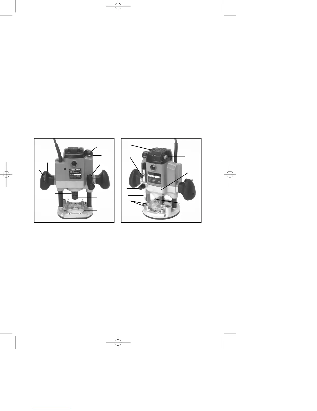
Fig. 8 Fig. 9
M
A On - Off Switch
B Switch Locking Button
C Plunge Locking Lever
D Collet Nut
E Chuck
F Micro Plunge Adjusting Knob
G Micro Plunge Adjusting Ring
H Clear Dust Cover
I On - Off Switch
J Depth Indicator/Knob
K Depth Rod Locking Knob
L Speed Control Knob
M Depth Stops
N Chip Deflector
O Dust Collector Inlet Tube
P Depth Rod
Q Spindle Lock