5
OPERATION
Beforeattemptinganyofthefollowingoperations,makesurethatthe
tool is switched off and unplugged and that the saw blade has stopped. Used saw
blades can be hot.
BLADE INSTALLATION (FIGURE B)
-Pushthesawbladelockinglever(3)upward.
-Withteethfacingforward,inserttheshankofthe
saw blade into the blade holder as far as it will go.
-Releasethelever.
-Checktoensurebladeissecurebeforecutting.
ADJUSTING THE SHOE FOR BEVEL CUTS
(FIGURE C)
Neverusethetoolwhentheshoeis
loose or removed.
The shoe plate can be set to a left or right bevel angle
ofupto45°.
To set the bevel angle:
-Pulltheshoebevelinglever(7)outandawayfrom
thesawtounlocktheshoe(6)asshowninfigure C.
-Slidetheshoeforwardtoreleaseitfromthe0°
positive stop position.
-Theshoecanbebeveledtotheleftortotheright
andhasdetentsat15°,30°and45°.
-Settheshoetothedesiredbevelangle.Usea
protractor to verify angle accuracy.
-Pushtheshoebevelingleverbacktowardsthesaw
tolocktheshoe.
To reset the shoe for straight cuts:
-Pulltheshoebevelinglever(7)outandawayfrom
thesawtounlocktheshoe(6)asshowninfigure C.
-Rotateshoetoanangleofapproximately0°andthenpullshoebackwardstoengage
the0°positivestop.
-Pushtheshoebevelingleverbacktowardsthesawtolocktheshoe.
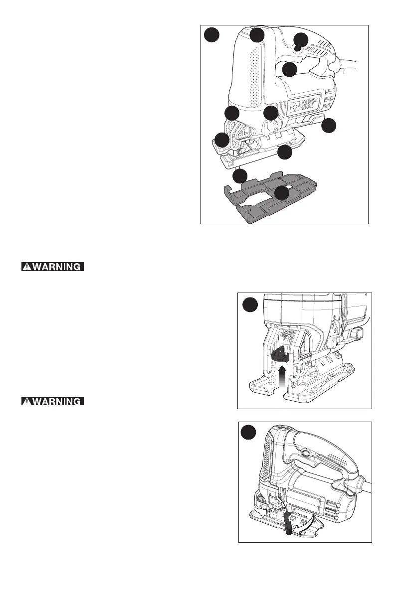
FUNCTIONAL DESCRIPTION
1. Trigger switch
2.Lock-onbutton
3.Sawbladelockinglever
4.Sawblade
5.Shoesleeve
6.Shoe
7.Shoebevelinglever
8.Speedcontrolwheel
9.Cuttingactionlever
10.LEDLight
1
2
3
4
5
6
8
7
9
A
10
B
C