11
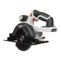
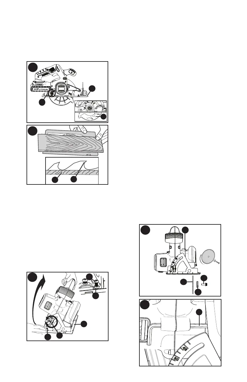
Move the saw shoe into the desired
position. The corresponding depth of cut
can be read from the scale (14).
one tooth (15) of the blade projects below
the workpiece (16) as shown in figure I.
Tighten the knob to lock the saw shoe in
place.
I
15
16
H
5
11
14
BEVEL ANGLE ADJUSTMENT -
FIGURE J
This tool can be set to bevel angles between
0° and 50°.
to unlock the saw shoe (5).
position. The
corresponding bevel angle can
be read from the scale (17).
to lock the saw shoe in place.
checking the bevel angle of an actual cut on
a scrap piece of material.
J
17
5
10
18b
18a
SHOE ADJUSTMENT FOR 90° CUTS
The shoe (5) has been set by the factory to
assure that the blade is perpendicular to the
shoe at 0° bevel setting.
square against the blade (7) and shoe (5) to
adjust the 90° setting.
adjustment screw (18b) (inset figure J)
so that the shoe will stop at the proper
angle. Retighten jam nut against the
shoe while holding adjustment screw in
position.
checking the squareness of an actual cut
on a scrap piece of material.
ATTACHING AND REMOVING THE
BLADE - FIGURE K - L
(7) and clamp washer (19) as shown in
figure K.
turning the blade bolt (20) with the blade
wrench (9) until the blade lock engages
and the blade stops rotating.
NOTE: Blade wrench is stored on the
saw as shown in figure L.
blade wrench.
NOTE:
loosen, turn clockwise. To tighten, turn
counterclockwise.
NOTE: Never engage the blade lock while
the saw is running, or engage in an effort
to stop the tool. Never turn the tool on
while the blade lock is engaged. Serious
damage to your saw will result.
K
20
19
7
13
L
9