EN
ECM5000 - ECM5000M - ECS5000 - ECS5000M - ECS8000 - ECS8000M
Surface mount or Mortice Electromagnetic locks
INSTALLATION MANUAL
The NO/NC signal only switches when the door
is closed with the power to it on.
4 position.eu.com
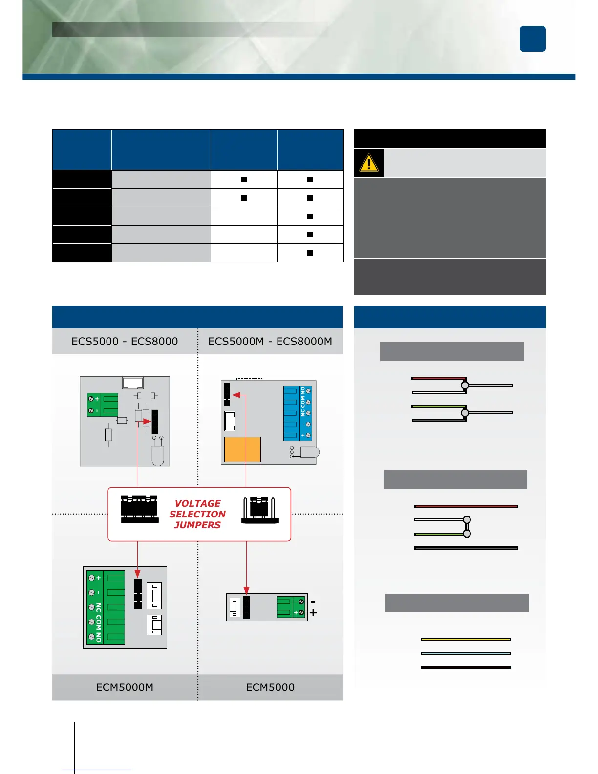
- Check the jumper position before connecting
the lock to the input current. A wrong position
could damage the lock. This type of damage
is not covered by the warranty.
- Make sure that the magnet and the armature
meet evenly over their entire mating surfaces.
The Armature plate must be able to pivot
slightly about its center mounting screw
to compensate for any door misalignment.
IMPORTANT NOTE
12V DC
Red
+
White
-
Green
Black
24V DC
Red
+
White
-
Green
Black
CONTACT
Yellow NC
Blue COM
Orange NO
12V dc Default setup
Terminal
block
Correspondence
ECS5000
ECS8000
ECM5000
ECS5000M
ECS8000M
ECM5000M
+ 12 or 24V dc
- - 0 V
N.C
NC (Normally closed)
-
COM
COM -
N.O
NO (Normally open)
-