MFG. #5401162 - REV C-1
12/10
PRINTED IN USA PAGE 2 OF 8
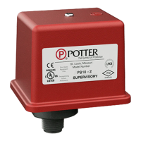
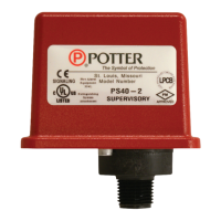
MODEL PS10 (VDS)
PRESSURE SWITCH
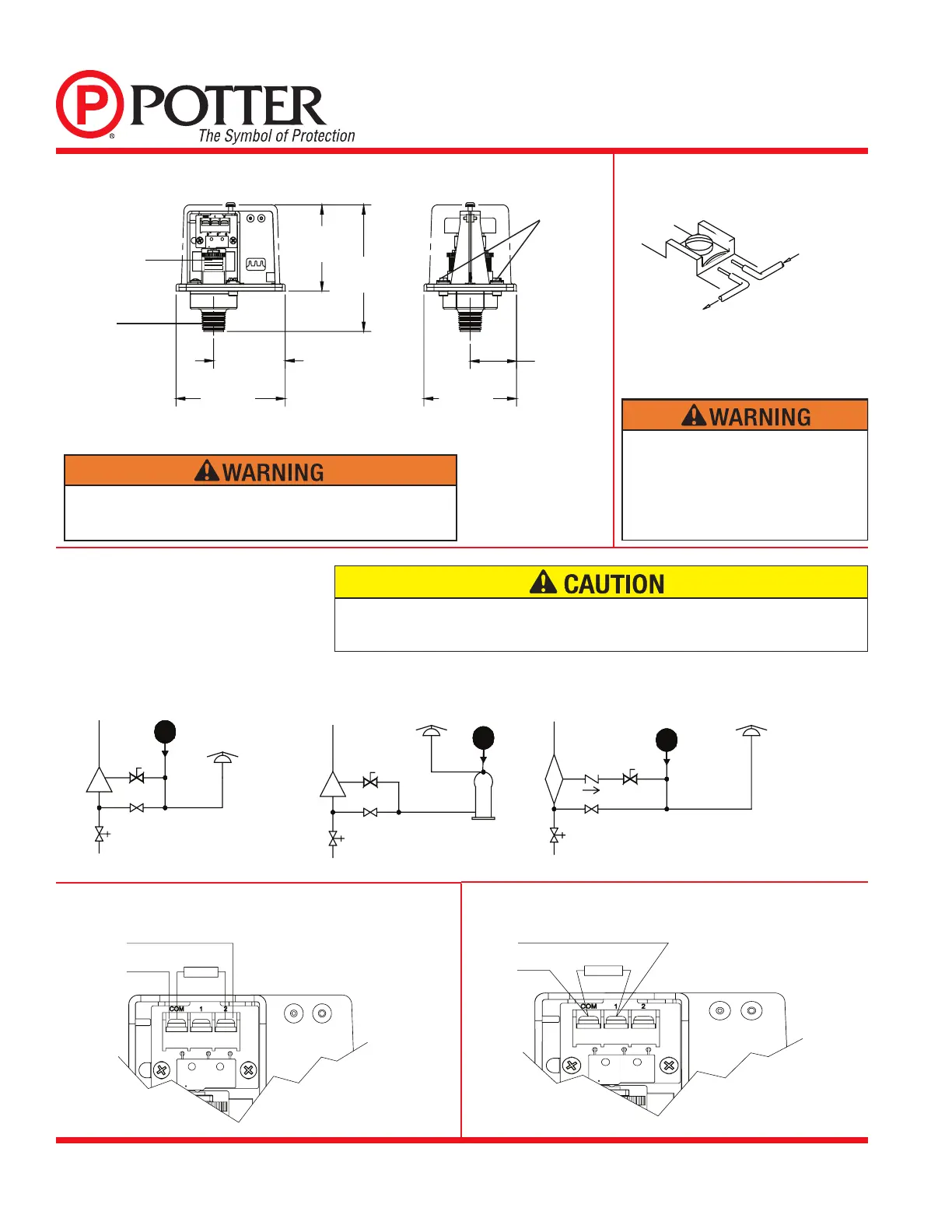
Typical Sprinkler Applications
Switch Clamping Plate Terminal
Dimensions
OUTGOING
INCOMING
DWG# 923-3
Closing of any shutoff valves between the alarm check valve and the PS10 will render the PS10
inoperative. To comply with NFPA-72 any such valve shall be electrically supervised with a
supervisory switch such as Potter Model RBVS.
Low Pressure Signal Connection
Waterow Signal Connection
WET SYSTEM WITH
EXCESS PRESSURE
WATER
MOTOR
GONG
PS10
RBVS
WET
SYSTEM
ALARM
CHECK
VA LVE
OS & Y
VA LVE
WATER
BY-PASS
VA LVE
WET SYSTEM WITHOUT
EXCESS PRESSURE
WATER
MOTOR
GONG
WET
SYSTEM
ALARM
CHECK
VA LVE
OS & Y
VA LVE
RBVS
WATER
BY-PASS
VA LVE
RETARD
PS10
DRY
SYSTEM
ALARM
CHECK
VA LVE
OS & Y
VA LVE
WATER
BY-PASS
VA LVE
CHECK
VA LVE
RBVS
DRY SYSTEM
PS10
WATER
MOTOR
GONG
DWG. #923-2AA
Fig. 2
Fig. 4
Fig. 5
Fig. 3
NOTE: To prevent leakage, apply Teflon tape sealant to male threads only.
ADJUSTMENT
KNOB
2.87
[72.97]
4.22
[107.19]
2.48
[62.87]
3.78
[95.89]
3.20
[81.28]
1.60
[40.64]
Fig. 1
GROUND
SCREWS
1/2" NPT
Use of pipe joint cement may result in obstruction of the aperture and loss
of signal.
An uninsulated section of a single conductor
should not be looped around the terminal and
serve as two separate connections. The wire
must be severed, thereby providing supervision
of the connection in the event that the wire
becomes dislodged from under the terminal.