EasyManua.ls Logo

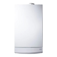
Potterton HE Plus User Manual

Potterton HE Plus
68 pages
To Next Page IconTo Next Page
Page #1 background imageLoading...
Page #1 background image
Supplied By www.heating spares.co Tel. 0161 620 6677
© Baxi Heating UK Ltd 2007
Installation & Service Instructions
Promax System
HE Plus
Range
These instructions include the Benchmark Commissioning Checklist
and should be left with the user for safe keeping.
Question and Answer IconNeed help?

Do you have a question about the Potterton HE Plus and is the answer not in the manual?

Potterton HE Plus Specifications

General IconGeneral
ModelHE Plus
CategoryBoiler
Fuel TypeNatural Gas
Efficiency RatingA
MountingWall-mounted
ERP RatingA
Domestic Hot Water Temperature Range35-60°C
Warranty2 years
TypeCombi
Central Heating Flow Temperature Range30°C - 80°C
Output40kW

Summary

Building Regulations and the Benchmark Commissioning Checklist

Legislation

Installation Regulations and Codes of Practice

Details legal requirements for installation and relevant codes of practice.

Safe Manual Handling

4.0 Technical Data

Promax System HE Plus Specifications

Lists detailed technical specifications for different boiler models.

5.0 Dimensions and Fixings

7.0 Site Requirements

Condensate Drain Installation

Provides instructions for installing the condensate drain pipe.

9.0 Plume Displacement

Determining Permissible Flue Lengths

Explains how to calculate permissible flue lengths using graphs.

10.0 Installation

Boiler Fitting and Pipework

Guidance on physically mounting the boiler and connecting pipework.

Flue and Electrical Connections

Instructions for fitting the flue and making electrical connections.

11.0 Commissioning

Boiler Commissioning Steps

Step-by-step guide for commissioning the boiler.

Checking Boiler Operation and Gas Rate

Procedures for checking gas rate and boiler operation.

13.0 Servicing

Annual Servicing Procedures

Instructions for performing annual boiler servicing.

15.0 Combustion Check

Checking and Adjusting CO2 Levels

Detailed procedure for checking and adjusting CO2 levels.

16.0 Electrical

Illustrated Wiring Diagram

Shows the electrical connections and layout of the boiler.

18.0 Fault Finding

Initial Fault Finding Checks and Error Codes

General checks and explanation of boiler error codes.

Troubleshooting Flowcharts

Flowcharts guiding troubleshooting based on operational sequence.

Fault Finding Solutions Sections A-L

Sections providing solutions for specific fault scenarios.

benchmark GAS BOILER COMMISSIONING CHECKLIST

Related product manuals