POTTERTON COMMERCIAL PRODUCTS DIVISION
INSTALLATION, OPERATION AND MAINTENANCE MANUAL
SECTION 4
PARAMOUNT
PAGE 15
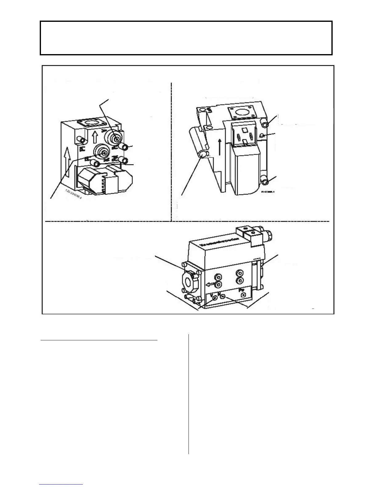
Fig. 6 gas valve (injector pressure settings can be made with 2.5 mm Allen key) (not provided)
fitting for
injector
pressure
Measuring
fitting for
supply
pressure
Adjustment screw for injector pressure (minimum load)
+ Clockwise: More gas
- Anticlockwise: Less gas
Kromschröder Co.CG 10…No.847 55 366
(PARAMOUNT 60)
Measuring fitting for
injector pressure
Adjustment for injector
pressure (full load)
+Anticlockwise: More
gas
- Anticlockwise: Less
gas
Measuring fitting for
supply pressure
Adjustment screw for injector pressure (minimum load)
+ Clockwise: More gas
- Anticlockwise: Less gas
Fabr. Kromschröder CG 120 Ro1-Vt2WF1
(PARAMOUNT 80)
Measuring fitting for
Adjustment screw for
injector pressure (minimum
load)
+ Clockwise: More gas
- Anticlockwise: Less gas
GUIDE VALUES FOR INJECTOR PRESSURE
Guide Values for Gas Flow Rate Injector Pressure
and CO2 Content: The values given in Table 3 are
guide values. It is important that the gas quantity is
set via the injector pressure so that the CO2 value is
within the specified values.
Boiler Control via 0 – 10V DC input signal (relay
clip-in module CISP): The boiler is provided with an
input for a 0-10V DC signal to control the boiler
temperature of the boiler output directly.
- to activate this function, set param 618 to 4 or 5
(see parameter for details)
- For a proper use of this input, disconnect all
external controls from the boiler (e.g. room control
RRG) and set the heating curve to “___” (parameters
532 and 533 see parameter listings).
NOTE: If another relay clip-in is installed (e.g. CIR,
CIST, CITF), the CISP must be taken out and
Parameter 618 must then be programmed according
to the installation manual of the specific clip-in
module.
 Loading...

