Supplied By www.heating spares.co Tel. 0161 620 6677
Boiler Heat Exchanger: 6.5 litres Cylinder
Small Bore Pipework: 1 litre per kW of The hot water cylinder must be an indirect coil type or a
system output direct cylinder fitted with an immersion calorifier
suitable for operating at a gauge pressure of 0.3 bar
Micro Bore Pipework: 7 litres (5lbf/in
2
) in excess of safety valve setting. Single feed
indirect cylinder are not suitable for sealed systems.
Steel Panel Radiators: 8 litres per kW of
system output Method of Make-Up
Low Water Capacity Radiators: 2 litres per kW of Provision shall be made for replacing water loss
system ouput from the system either:-
i) from a make-up vessel or tank mounted in a
Hot water Cylinder: 2 litres position higher than the top point of the system,
and connected through a non-return valve to the
If the system is extended, the expansion vessel volume system on the return side of hot water cylinder
may have to be increased unless previous provision has or the return side of all heat emitters.
been made for the extension. Where a vessel of the or
calculated size is not available, the next available larger
size should be used. The boiler flow temperature is ii) where access to a make-up vessel would be
controlled at approximately 82ºC. difficult by using the mains top up method or
a remote automatic pressurisation and make-up
unit as sillustrated in FIG. 7 METHODS 1 and 2.
The vessel size can now be determined from the following
table where V=System volume in litres. Mains Connection
Vessel Charge Pressure (bar) 0.5 1.0
There shall be no connection to the mains water
Initial System Pressure (bar) 1.0 1.0
supply or to the water storage tank which supplies
Expansion Vessel Volume (litres) Vx0.11 Vx0.087
domestic water even through a non-return valve,
without the approval of the local Water Authority.
Further guidance is given in BS 5449 Part 1 or BS 7074
Part 1. Filling Point
The system shall be fitted with a filling point at low
level which incorporates a stop valve to BS1010
and a double check valve (approved by the National
Water Council) to be fitted in this order from the
system mains, Refer to FIG. 7. Method 1.
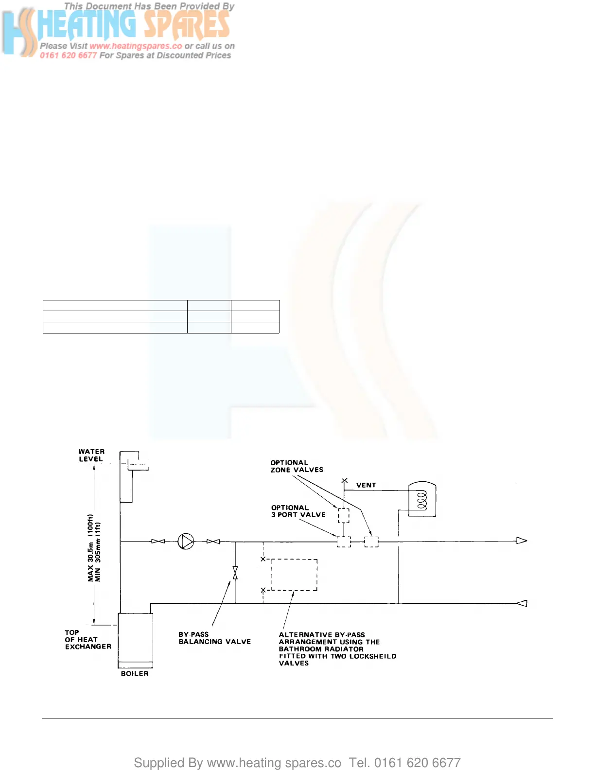
FIG. 6 OPEN VENTED FULLY PUMPED SYSTEM
FITTED WITH A COMBINED FEED AND VENT
 Loading...