TECHNICAL
DATA
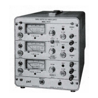
·lRIPlE
OUTPUT
LABORATORY
POWER
SUPPLY
T
2
L,
COS/MOS
AND
ANALOG
APPLICATIONS
MODEL
TP343
A
electrical
specifications:
Sources
A & B
(1)
0·20V, 0·2.SA
Parameter
each
output
INPUT:
105·125, 58-440 Hz
OUTPUT 0·20V, 0·2.5A
10·25V
, 0·1A
LOAD REGULATION:
0.01% + 1 mV per amp
LINE REGULATION:
0.01%
+0.5
mV
STABILITY
(2)
0.
02
%
+1
mV
RECOVERY TIME
(3)
100
us
CURRENT LIMIT
2
%·
105%
of
rated current
TEMPERATURE
0-
50
'C
TEMP. COEFFICIENT
0.02% + 300 uV
l'C
OV
CROWBAR
Adj.
~
3·30V
(4)
TRACKING
0.1%
+10mVby
front panel
switch
VOLTAGE CONTROLS
10
turn
potentiometer
FAULT INDICATORS
Lamp
indicates
short
circuit and overload
METERING
Dual range volt/ammeter
(1)
Sources A & B have one common terminal
*SOURCE
A
*SOURCE
B
SOURCE
c
IMPROVED
SPECIFICATIONS
-(
0-20
VDC,0-2.5A
/
0-25
VDC,0-lA
0-20
VDC,0-2.5A
/
0-25
VDC,0-lA
0-6
VDC,0-5A
I
0-15
VDC,0-2.5A
-
j>_
'Independent
or
0.1
%
tracking
with
panel
switch
NOISE
&
RIPPLE
LESS
THAN
lmV
P-P
source C
0·6V,
0-SA
C).1SV,
0-2.SA
0-6V
, 0·5AI 0-15V, 0-2.5A
0.
01
% + 1 mV per amp
0.01
% + 0.5 mV
0.
02
% + 1 mV
100
uS
2%-105%
of
rated current
0·
50
'C
0.02% + 300
uV/'C
Adj. 3·20V
10
turn
potentiometer
Lamp indicates short
circuit and overload
Dual range volt/ammeter
features:
• No derating. All
outputs
may be operated simul·
taneously at f
ull
capacity
for
a
maximum
of 140W.
•
Outputs
are floatin'Q
with
respect
to
each
other
and chassis except for an _internal connection
between one negative terminal and one
positive
terminal
of
the
20
volt sources. The
two
20
volt
sources may be operated in series
to
prov
ide
0
-40
VDC, 0·2.
5A
in any pol
arity
with
respect
to
chassis
or
left
floating. The 0
·1
5V
source may be
operated
in
any polarity
with
respect
to
chassis
or
left floating.
• Independent
adjustment
of
each
output
voltage
utilizing
10·turn
potentiometers
with .05% reso-
lution
.
• Separate current
limit
ing
adjustment
for
each
output.
• Separately adjustable overvoltage crowbars on
each output. Overvoltage crowbars on 0·20V out·
puts
trip simultaneoulsy
if
either
one operates.
(2)
24
hours at
constant
lin
e,
load and ambient temperature
• Three taut band suspension dual range meters
individually selectable for voltage
or
current of
each source.
(3)
To recover
to
within
15
mV on nominal
for
a 10%·100% load change
(4)
Both sources
will
crowbar
if
either one operates
mechanical
specifications:
DIMENSIONS: 8'1•' H x 73A' W x
13
V2'
D.
WEIGHT:
20
lbs.
FINISH: Natural anodized
aluminum
panel; blue
vinyl enamel cabioet,
with
carrying handle.
• A
"F
AULT"
indicator
lamp on each
output
signals
overload, short circuit, crowbar trip or current
limit operation.
•
Automatic
voltage tracking
of
the 0-20 VDC
sources
to
:1:
0
.1
% by means
of
a panel toggle
switch
. This
switch
is equipped
with
a locking
lever
to
prevent accidental operation. Single
potentiometer
control
of
tracking outputs.
•
Outputs
may be shorted
into
each
other
in any
polarity
without
damage.
POWER
DESIGNS
POWER
DESIGNS
INC.
17
00
SHAMES
DRIVE
•
WESTBURY,
N. Y. 11590
Te
l:
516-333
-
6200
•TWX
510
-
222
-6561
POWER
DESIGNS
PACIFIC
INC
.
3381
MIRANDA
AVENUE
•
PALO
ALTO
.
CALIF
.
94304
Tel
:
415-493-6111
•TWX
910-373-1251