SECTION 3
PRINCIPLES OF OPERATION
This voltage regulated
power
supply
uses three
"linear
mode"
(series regulator)
systems
to
obtain
output
voltage regulation,
low
ripple and
low
noise
characteristic.
The
"linear
mode"
technique,
consists
basically
of
the
insertion
of
an
electronically
controlled
variable
impedance
(series
regulator) between a DC unregulated
source
and the
output
terminals
of
the
equipment.
Since
the
outputs
are very
similar
in
performance
we
will
describe
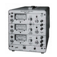
Source C
which
is
slightly
more
complex
due
to
its
dual
output
rating
characteristics.
T1
transformer
secondary
(terminals
15, 16,
17)
in
conjunction
with
bridge
rectifier
CR307 and
capacitors
C313, C314 and C315,
produces
two
unregulated
DC
power sources,
which
in
conjunction
with
series
regulators
0306, 0307,
0308
and driver 0304, provide the
output
power
of
the supply.
If
the
output
voltage
requirements
(as
determined
by the
output
VOLTAGE
control
setting)
is
below
the
voltage provided by the
unregulated
capacitors
C314, C315, the active series
regulators
will
be
0307
and 0308.
0306
will
operate as a driver.
If
the
output
voltage requirements are above the voltage pro-
vided by C314, C315, then the energy
will
be
supplied
by the series
capacitor
combination
of
the
above
mentioned
and C313 (from C313 +
to
C314-
).
0306
will
become the series
regulator
and
the
base
to
emmiter
junctions
of
0307
and
0308
will
act
as a
diode
in series
with
the
power
path.
Transformer
secondary
(terminals
13,
14)
in
conjunction
with
rectifier
CR301 and
capacitor
C301
pro-
duces an
unregulated
DC
source used
to
generate a B + superregulated bias
voltage
and a B -
semi-regulated
voltage
for
amplifier
operation. Both bias voltages are
connected
to
the
DC+
output
of
the
power
supply.
The B +
bias
voltage is generated by VR303 (main reference
of
the overall source), R301-R305,
C302-C304, VR301, 0301 and
U301
B.
This
circuit
produces, across C304, a very
stable
and
low
ripple
voltage between 12.4 voe and 13.2 voe.
The B - bias voltage, generated by zener
diode
VR302,
should
have a
voltage
between 5.0 VDC and
5.8 voe.
The variable
resistor
divider
(R315,
R325
and
R344)
compares
the
output
voltage
of
the
supply
with
the B + voltage; the
differential
voltage is then fed to the
input
of
voltage
comparator
amplifier,
U301A, whose
output
in
conjunction
with
current
amplifiers
0303
and
0304
modify
the drive
of
the
series
regulators
previously
mentioned,
to
maintain
voltage regulation.
The voltage developed
across
R333
(current sensor) due
to
external load currents, is used
for
am-
meter readings. It is
also
continuously
compared
to
B + by means
of
a
resistor
divider
(R310,
R311
and
R342)
at
amplifier
U301D.
If
the non-inverting
input
(pin
12)
becomes
lower
in
voltage
than the in-
verting input, (pin
13)
U301
D
will
be
activated
and operate
through
CR303 and CR304
to
decrease the
drive on 0303,
thus
limiting
the drive
to
the series regulators and hence the
current
of
the
power
sup-
ply.
Due
to
the dual rating
of
this
supply,
it
is
imperative
to
protect
0306
when
it
is
acting
as a series
regulator. Under
this
condition,
the main load
current
goes
through
R330;
its
voltage is
once
again
compared
to
the B + by
amplifier
U301C,
limiting
the current
flow
on
0306
to
approximately
2.75A.
If
either
U301C
or
U301
D is activated,
they
will
operate 0302, driving
power
to
the FAULT lamp,
DS301.
The variable
resistor
divider
(R321,
R343)
compares
the
output
voltage
with
B + at the base
to
em-
miter
junction
of
0305. Depending on the
setting
of
R343
(overvoltage
control)
and the
output
voltage
of
the source,
0305
will
be activated,
firing
the
silicon
control
rectifier
CR309,
producing
a
short on the
output
of
the supply, hence
protecting
the user's load.
This
short
will
make the
power
supply
go
inot
a
"FAULT"
mode. If an overvoltage on the
supply
is produced by
failure
of
the
control
circuits,
there is a
possibility
that
secondary
protection
fuse
F301
will
blow, in
which
case there may
not be a
"FAULT"
indication.
-5-
 Loading...