1.1
GENERAL
INSTRUCTION MANUAL
SECTION 1
INTRODUCTION
This
manual
contains
instructions
for
the
installation,
operation
and
mainentance
for
Power
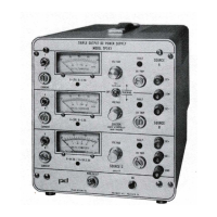
Designs Model TP340 and TP343A
triple
output
DC
regulated
power
supply.
1.2 DESCRIPTION
This
triple
output
regulated
DC
power
source is
suitable
for general purpose
laboratory
and
industrial
applications.
It features
adjustable
and
independent
current
limiting
and over-
voltage
crowbar
protection
for each
output.
A
fault
lamp
indicates
crowbar
operation
or
an
overload
condition.
The
following
description
refers
to
the
three
outputs
as Source A
("A"},
Source B
(''B")
and
Source C
("C")
respectively.
The
power
supplied
by
"A"
and
"B"
is
obtained
from three
binding
posts
on the
front
panel.
The COMMON
terminal
is the
internal
connection
between the negative
terminal
of
"A"
and
the
positive
terminal
of
"B".
This
terminal
is
isolated
from
ground
and
both
terminals
of
"C".
The
DC+
terminal
on source
"A"
produces
a
positive
voltage
with
respect
to COMMON. The
DC
-
terminal
on source
"B"
produced a negative voltage
with
respect
to
COMMON. Power
from these
terminals
can
also
be
obtained
directly
from
DC+
to
DC - . In
that
case the out-
put voltage
will
be the sum
of
the
"A"
and
"B"
voltages.
A
front
panel TRACKING
switch
provides
individual
control
of
each source
or
automatic
Master/Slave operation. In
this
mode
source
"B"
tracks
source
"A".
Source
"C"
provides
power
by means
of
two
binding
posts
that
are
isolated
from ground.
This source may be operated in
either
polarity
with
respect to
chassis
or
left
floating.
All
outputs
may be operated
simultaneously
at full
capacity
with
no derating.
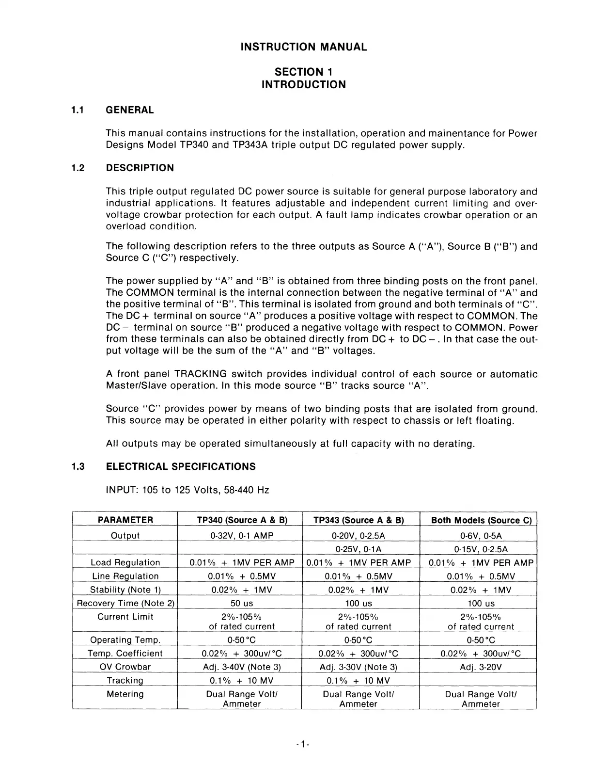
1.3 ELECTRICAL SPECIFICATIONS
INPUT: 105
to
125 Volts, 58-440 Hz
PARAMETER TP340 (Source A &
B)
TP343 (Source A &
B)
Both Models (Source
C)
Out_e_ut
0-32V,
0-1
AMP
0-20V, 0-2.5A 0-6V, 0-5A
0-25V, 0-1A
0-15V, 0-2.5A
Load
Re_g_ulation
0.01
% + 1 MV PER
AMP
0.01
% + 1MV
PER
AMP
0.01
% + 1 MV
PER
AMP
Line
Re_g_ulation
0.01
% + 0.5MV
0.01
% + 0.5MV
0.01
% + 0.5MV
Stabili!Y_J_Note
11
0.02% + 1MV 0.02% + 1MV 0.02% + 1 MV
Recovery_ Time
lNote
2)
50 us 100 us
100 us
Current
Limit
2%-105% 2%-105%
2%-105%
of
rated
current
of
rated
current
of
rated
current
02_eratin_g_
Temp. 0-50°C 0-50
°C
0-50°C
Tem_g.
Coefficient
0.02% + 300uv/°C
0.02% + 300uv/°C
0.02% + 300uv/°C
OV
Crowbar
Adj. 3-40V
lNote
31.
Adj. 3-30V (Note
3l_
Adj. 3-20V
Tracking
0.1% +
10
MV 0.1% +
10
MV
Metering
Dual Range
Volt/
Dual Range
Volt/
Dual Range
Volt/
Ammeter
Ammeter
Ammeter
-1
-