Installation and Operator’s Manual Page 11 of 20
(Aurora Wind Interface Rev 4.0)
2 WBI Connections
WARNING: Always safety brake the wind turbine and disconnect the AC grid Circuit
Breaker before opening the WBI.
2.1 Required System Connections
In the following table are shown input and output pass through openings and glander
to be used for the US version (not provided) and provided plastic glander sizes for all
other non US versions.
I/O Connection Required Knock-out
Trade Size (US)
Glander (others)
Wind Speed Optional PG 9 = 3/8” M16
Wind Input Yes PG 16 = 3/4 “ M32
Diversion Load Optional* PG 16 = 1/2 “ M25
Bulk Out Yes PG 21 = 3/4 “ M25
Table 3: Required Connections, Knock-out Size and glanders
* This connection is optional if the wind turbine will self-limit and prevent its output
voltage from exceeding 410Vac (580Vdc) under any condition.
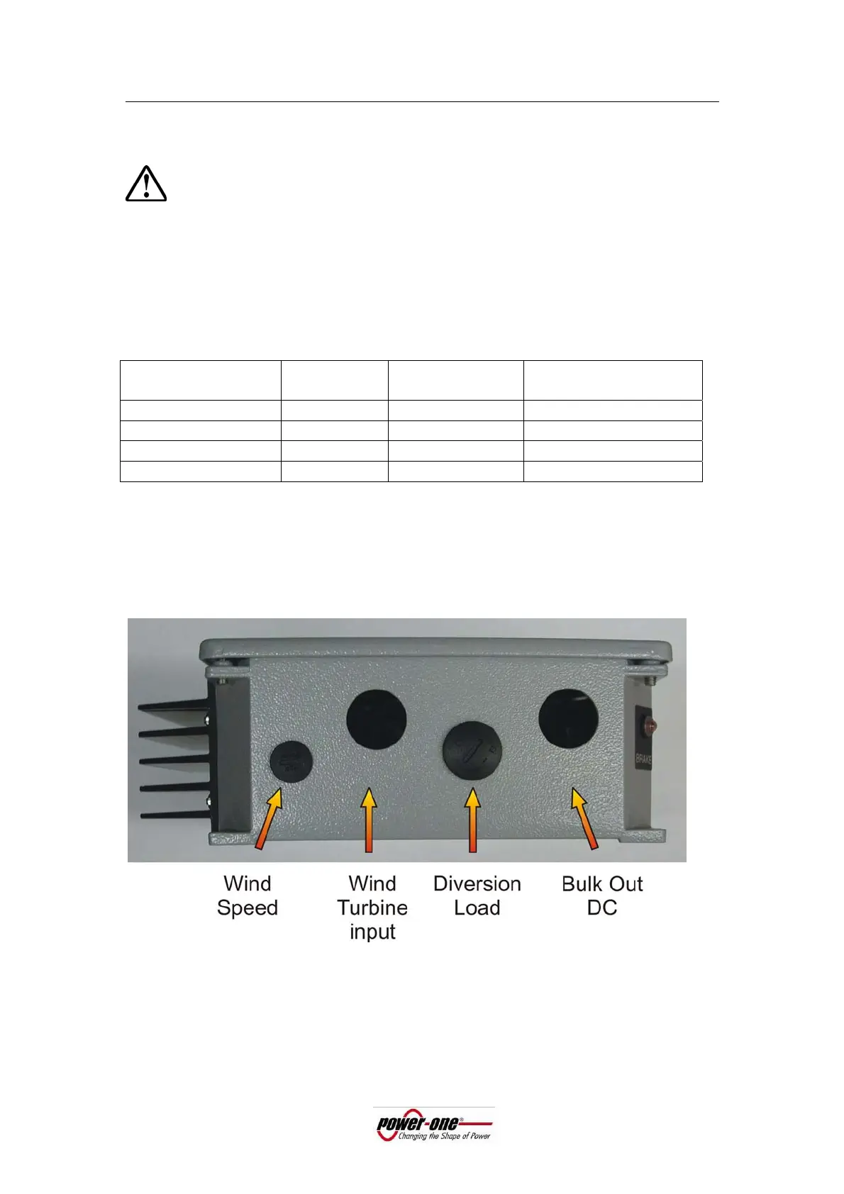
Figure 3: Knockout designations for US version; optional openings are provided
with plastic fittings; input and output openings are supplied temporarily covered
by detachable labels.



 To Next Page