Installation and Operator’s Manual Page 9 of 20
(Aurora Wind Interface Rev 4.0)
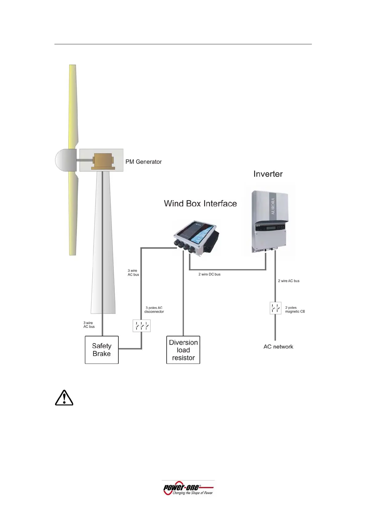
1.3 System Block Diagram
Figure 2: Typical Wind System block diagram
The wind turbine must have a primary safety means of limiting the wind turbine speed, this
typically is a some type of furling method, blade stalling, self limiting airfoil design, electric
safety brake or any other system may exist
.
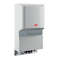
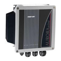
Power-One supplies the products detailed with pictures in the above block scheme.