11
WARRANTY
CENTER
C
E
R
T
I
F
I
E
D
SECTION 1.7 – Electronics & Controllers
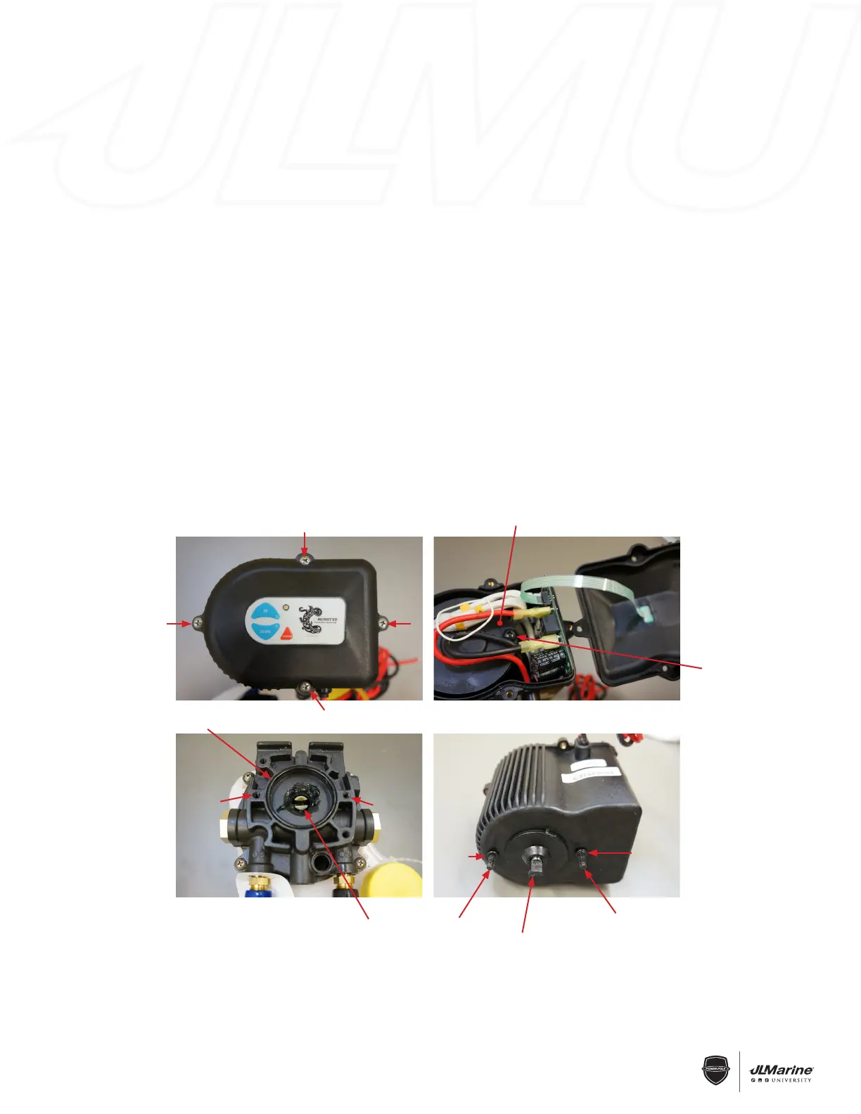
C-Monster 1.0 Motor Assembly Installation
REMOVAL:
STEP 1 Disconnect the RED 12V (+) and BLACK 12V (-) wires from the Battery Source.
STEP 2 Remove Motor Cover by unscrewing the four Phillips Head Bolts attach the Cover to the Motor Assembly.
FIG 1
STEP 3 Loosen the two Phillips Head Bolts that hold the Motor to the Pump Base approximately 5/8”. FIG 2
STEP 4 Lift the Motor Assembly off of the Pump Base.
INSTALLATION:
STEP 1 Using a flat-bladed screwdriver, line the Pump Coupler up with the two Motor Bolt Holes. FIG 3
NOTE: Ensure that the O-Ring surrounding the Pump Coupler is installed.
STEP 2 Turn the Motor Shaft by hand until it lines up with the Two Motor Bolts. FIG 4
NOTE: Ensure that the Two Motor Bolts have O-Rings installed.
STEP 3 Follow REMOVAL STEPS 3 & 4 in reverse order, ensuring that the Motor Shaft mates properly with the
Pump Coupler.
STEP 4 Re-install the Motor Cover with the four Phillips Head Bolts.
STEP 5 Re-connect the RED 12V (+) and BLACK 12V (-) wires to the Battery Source.
Figure 1 Figure 2
Phillips-Head Bolt
Figure 3
Pump Base
O-Ring
Motor Bolt
Hole
Motor Bolt
Hole
Pump
Coupler
Figure 4
Motor
Bolt
Motor
Bolt
Aligned Motor
Shaft
O-Ring
O-Ring
Motor
 Loading...