32
WARRANTY
CENTER
C
E
R
T
I
F
I
E
D
C-Monster HPU Removal / Installation (continued)
INSTALLATION:
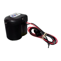
STEP 1 Fill the reservoir of the replacement HPU to the FULL line with fresh Green Marine.
STEP 2 Attach the new HPU to the Mounting Bracket with the Bolts and Tighten with 9/16” Wrench.
STEP 3 CM1 Remove the Dust Cap, Nut, and Ferrule from the Compression Fittings on the pump.
NOTE: You may reuse the Nut and Ferrule already on tubing.
STEP 4 CM1 Insert Hydraulic Tubing into corresponding Hydraulic Fitting (UP and DOWN) on HPU and
tighten the nuts with 9/16” Wrench. FIG 2-A
CM2 Attach corresponding fitting (UP and DOWN) to HPU and finger tighten. Turn the Hydraulic
Fittings a quarter turn using a 5/8” Wrench. FIG 2-B
WARNING! CM1 Hydraulic failure may occur if the Nuts are not tightened down far enough so that none of
the compression fitting’s threads are visible.
STEP 5 Connect power to the HPU. The LED indicator light should be flashing GREEN, indicating the unit has
power.
See Electronics and Controllers Section 1.9 for programming HPU.
IImmppoorrttaanntt:: TThhee ttuubbiinngg nneeeeddss ttoo ppaassss tthhrroouugghh tthhee ffeerrrruullee ffaarr eennoouugghh ssuucchh tthhaatt tthheerree iiss aapppprrooxxiimmaatteellyy aa 11//22””
lleennggtthh ooff ttuubbiinngg eexxppoosseedd.. ((SSeeee IImmaaggee ##55))
D. Insert the blue tubing into the compression fitting labeled UP (blue dust cap), and the black tubing into the
fitting labeled DN (black dust cap). While holding one length of tubing fully inserted into its respective
compression fitting base, begin threading the compression fitting nut onto the base. Repeat this step for the
remaining length of hydraulic tubing.
E. Tighten both compression fitting nuts with a 9/16” wrench while simultaneously holding their respective bases
with a 1/2" wrench. ((SSeeee IImmaaggee ##66))
WWaarrnniinngg:: TThhee nnuuttss mmuusstt bbee ttiiggh
htteenneedd ddoowwnn ffaarr eennoouugghh ssuucchh tthhaatt NNOONNEE ooff tthhee ccoommpprreessssiioonn ffiittttiinnggss’’ tthhrreeaaddss aarree
vviissiibbllee;; ootthheerrwwiissee,, hhyyddrraauulliicc ffaaiilluurree mmaayy ooccccuurr.. ((SSeeee IImmaaggee ##77))
F. Once all of the hydraulic tubing has been securely fastened, refer back to the “Owner’s Manual” for the
remainder of the Power-Pole shallow water anchor installation.
IImmaaggee ##77
NNUUTT MMUUSSTT CCOOVVEERR AALLLL TTHHRREEAADDSS!!
Figure 2-A
5/8” wrench
1/4 Turn
Figure 2-B
SECTION 2.2 – Hydraulic Systems

 Loading...