- 12 -
NOTE:
(1)The above electrical wiring diagrams are only for your reference, please subject the heat
pump to the posted wiring diagram.
(2)The swimming pool heat pump must be earthed well, although the unit heat exchanger is
electrically isolated from the rest of the unit .Earthing the unit is still required to protect you
against short circuits inside the unit .Bonding is also required.
Disconnect: A disconnector (circuit breaker, fused or un-fused switch) should be located
within sight of and easily accessible from the unit .This is common practice on commercial
and residential heat pumps. It prevents remotely-energizing unattended equipment and
permits turning off power to the unit while the unit is being serviced.
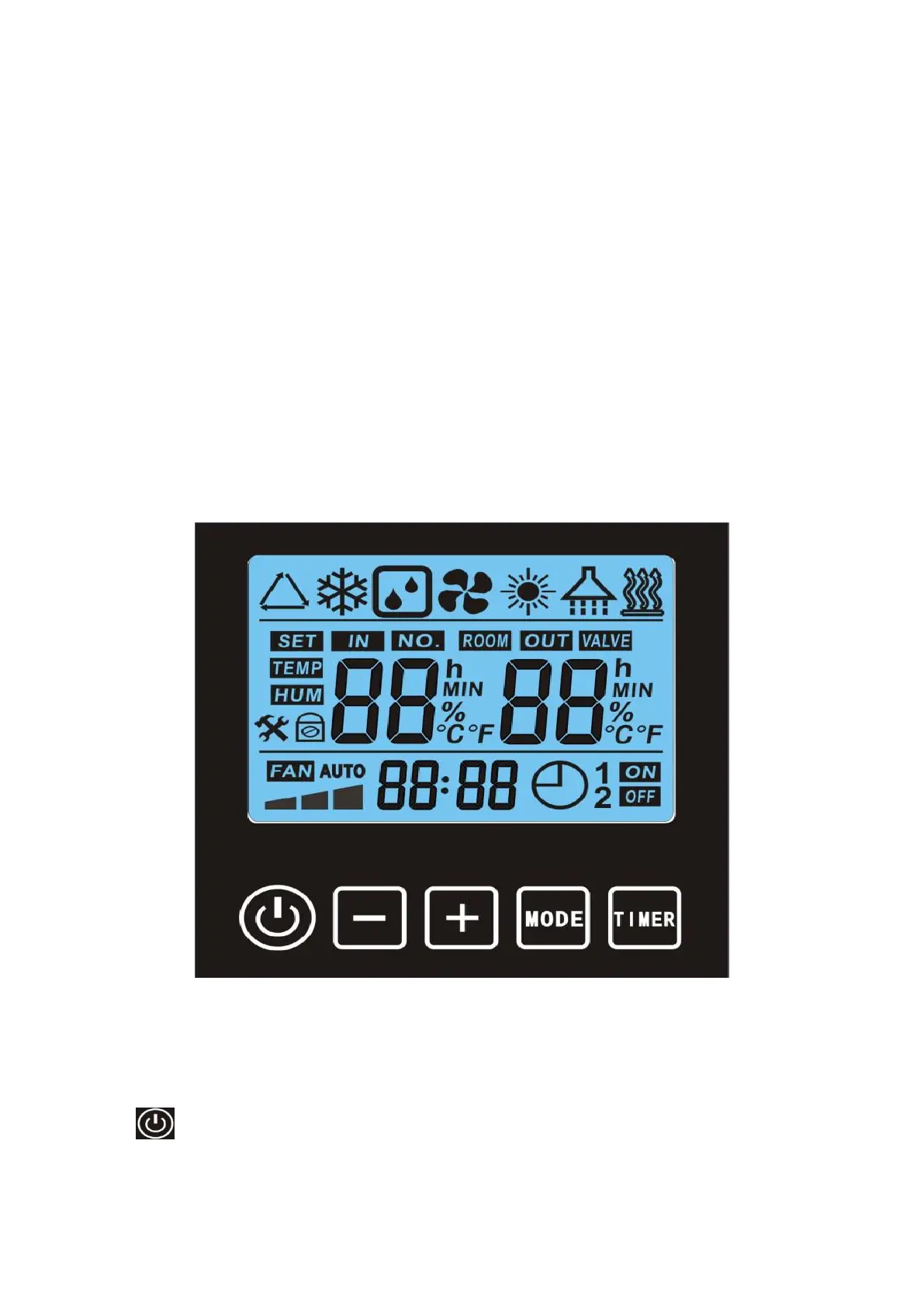
6. Display Controller Operation
6.1
The buttons of LED wire controller
When the heat pump is running or standby, the LED display shows the inlet water
temperature and setting temperature.
6.2 Start/stop the heat pump.
Press to start the heat pump, the LED display shows the desired water temperature for
5 seconds, then shows the inlet water temperature.