5.4 The pin of computer interface port:
The pin of computer interface port has the following characteristics:
5.4.1. Pin 6 and 8 are open collector outputs that must be pulled up to a common referenced
supply no greater than DC +40V. The transistors are capable of a maximum
nonconductive load of DC 25 mA, Use only pin 5 as the common.
5.4.2. Pin 8 generates a high to Low signal when the battery inside the UPS has less than 2
minutes back up time left.
5.4.3. Pin 6 generates a high to Low signal when the line is fail.
5.4.4. The UPS will shut down when a high RS-232 level is sustained on pin 3 for 0.36 seconds.
5.4.5. Pin 2 is the RS-232 data output.
5.4.6. Pin 3 is also RS-232 data input (RxD)
NOTE:
1. Switch rating +40V, 0.25A non-inductive.
2. Pin 5 should be connected to ground only.
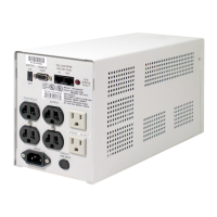
Communicating Interface Port
We provide a standard RS232 line (that is compatible with DB9 line) socket on the
rear panel of UPS. That port possesses several signals as explained below: