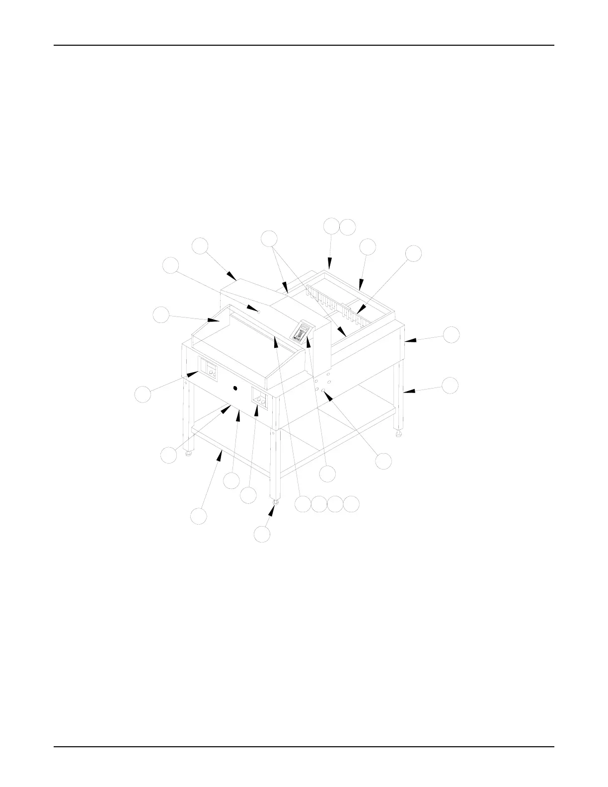
2.0 Nomenclature
1. Chassis - Houses the electrical and mechanical components.
2. Stand - Consists of legs and shelves. The stand can be separated from the chassis.
3. Keyboard Control - 20-character, 2-line Liquid Crystal Display at the top with a keypad below.
4. Right Switch Panel - Contains key switch, clamp switch, and blade switch.
5. Left Switch Panel - Contains On/Off toggle switch, reset switch, and clamp/blade switch.
6. Ready Light - Amber light indicates when safety conditions are met and the machine is ready for the next cutting cycle.
7. Paper Guides - Guide paper and maintains paper position.
8. Rear Safety Cover - Fixed cover over the rear deck.
9. Back Gauge - Controls the movement of paper through the cutting area.
10. Knife - Honed steel blade provides cutting action.
11. Clamp - Secures paper during the cutting process.
12. False Clamp - Can be attached to the bottom of the permanent clamp.
13. Cutting Stick - Protects the knife edge at the bottom of the cutting cycle.
14. Leg Levelers - Adjustable feet ensure a level cutting surface.
15. Storage Shelf - Front and rear shelves for operator convenience.
16. Fuseholder - The fuseholder (located under the front portion of the chassis) contains replaceable power fuses.
17. Circuit Breaker - Resettable circuit protector located under the front portion of the chassis.
18. Shroud - Housing for the blade and clamp drive components.
19. Serial Label - Identifies the serial number, electrical ratings, and agency approvals.
20. Line Cord - Connects the electric cutter to the AC power source.
21. Blade Adjustment - Compensates for blade wear/sharpening.
22. Front Safety Cover - Interlocked front deck cover.
23. Side Tables - Optional accessories to add working surface area to one or both sides.
PowerLine
TM
Operating Instructions
2