8. Set Up - Press this key to enter setup for programming the automatic mode cutting positions.
9. Enter - Press this key to install the operator entries into the operating system, or to review the current setup.
10. Mode - Press this key to toggle the operating mode to manual or automatic, or to select a stored setup.
4.0 Installation
WARNING! To prevent serious personal injury, always use a mechanical lifting device, such as a fork lift
or pallet jack, to move the machine or to separate the chassis from the frame.
NOTE: Place the cutter on a flat, level foundation sufficient to support its weight. Be sure to allow ade-
quate work space on all sides of the cutter.
4.1 Leveling the Machine
Level the cutter (check the top surface in two planes) by adjusting the leg leveler in the
bottom of each stand leg. Turn the leg leveler clockwise to shorten the leg length. Turn
the leg leveler counterclockwise to increase the leg length.
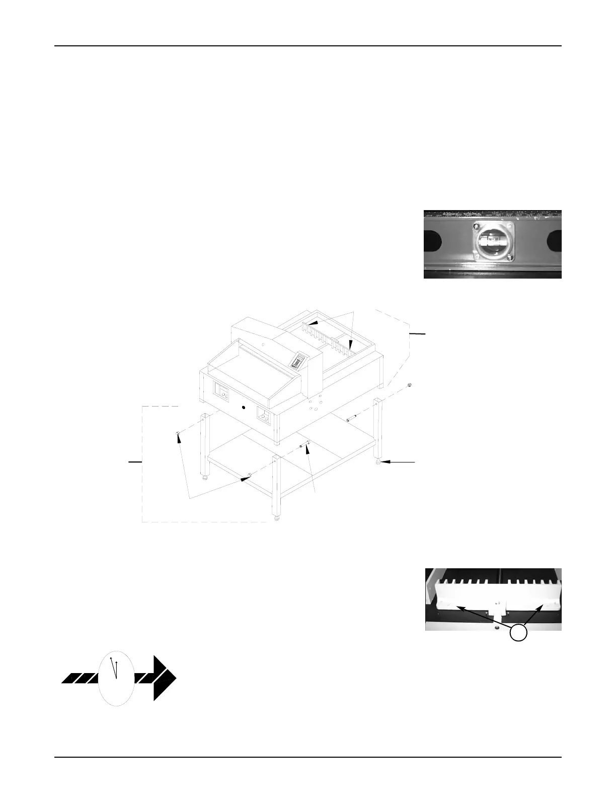
4.2 Releasing the Back Gauge
To prevent shipping damage, the back gauge is locked in place by two thumb screws(1)
located near the ends of the top rear surface of the back gauge. Remove these screws
before operating the electric cutter. To do so, first remove the rear safety cover by loos-
ening the crosspoint screws holding the cover to the rear of the shroud and the decks.
Remove the two thumb screws that secure the back gauge and reattach the safety cover.
4.3 False Clamp
The false clamp, made from clear polycarbonate, is used to reduce bruising (marking)
on carbonless paper. It is not necessary to use the false clamp when cutting standard
paper stock. Use of the false clamp affects the minimum cutting distance. When
installed, the minimum cutting distance is 2.370". When not installed, the minimum cut-
ting distance is 1.370". Section 6.0, Operation, includes the false clamp set up informa-
tion. The false clamp is held in place by four (three on the 21" EC) 10/32x3/8 flathead
hex socket screws. To install the false clamp, proceed as follows:
PowerLine
TM
Operating Instructions
4