Open
Close
Stop
Common
COM
COM
COM
24V
AC
2
4V
AC
ALT
RDO
OPN
CRO
FRE
OPN
CLO
STO
COM
CLOSE
PUSH
STOP
PUSH
CLOSE
P
HOTO
OPEN
PHOTO
LD16
LD17
LD13
OPEN CLOSE
FORCE
ADJUSTMENT
TB1
U4
COM
COM
COM
24V
AC
24V
AC
ALT
R DO
OPN
C RO
FRE
OPN
CLO
STO
COM
COM
COM
OPN
PHO
CLO
PHO
SHW
REV
OPN
EDG
C
LO
EDG
MST
OPN
MST
CLO
COM
COM
COM
OPE N
PUSH
FR EE
EX T
ALT
RADIO
OPN /
CLO
RADIO
OPE N
CL OSE
PUSH
STOP
PUSH
CL OSE
PHO TO
O
PE N
PHO TO
LD 18
LD 10
LD 11
LD 12
LD 15
LD 14
LD 16
LD 17
LD 13
O PEN
CLOS E
STO P
O PEN C LOS E
F ORC E
ADJ USTMENT
AUTO
RECL OSE
T IME R
O FF MAX
MID
L IMI T
REV
LOOP
OPN
EDG E
CLO
EDG E
R H OP N
LH C LO
LIM IT
RH CLO
LH OPN
LIM IT
MOTOR
OPE N
MOTOR
CL OSE
SHADOW
LOOP
LD19
LD2
LD3
LD4
LD5
LD6
LD8
LD9
LD7
1 2 3 4 5
POWER
LD1
P3
P4
TB1 TB2
U1
U2
U4
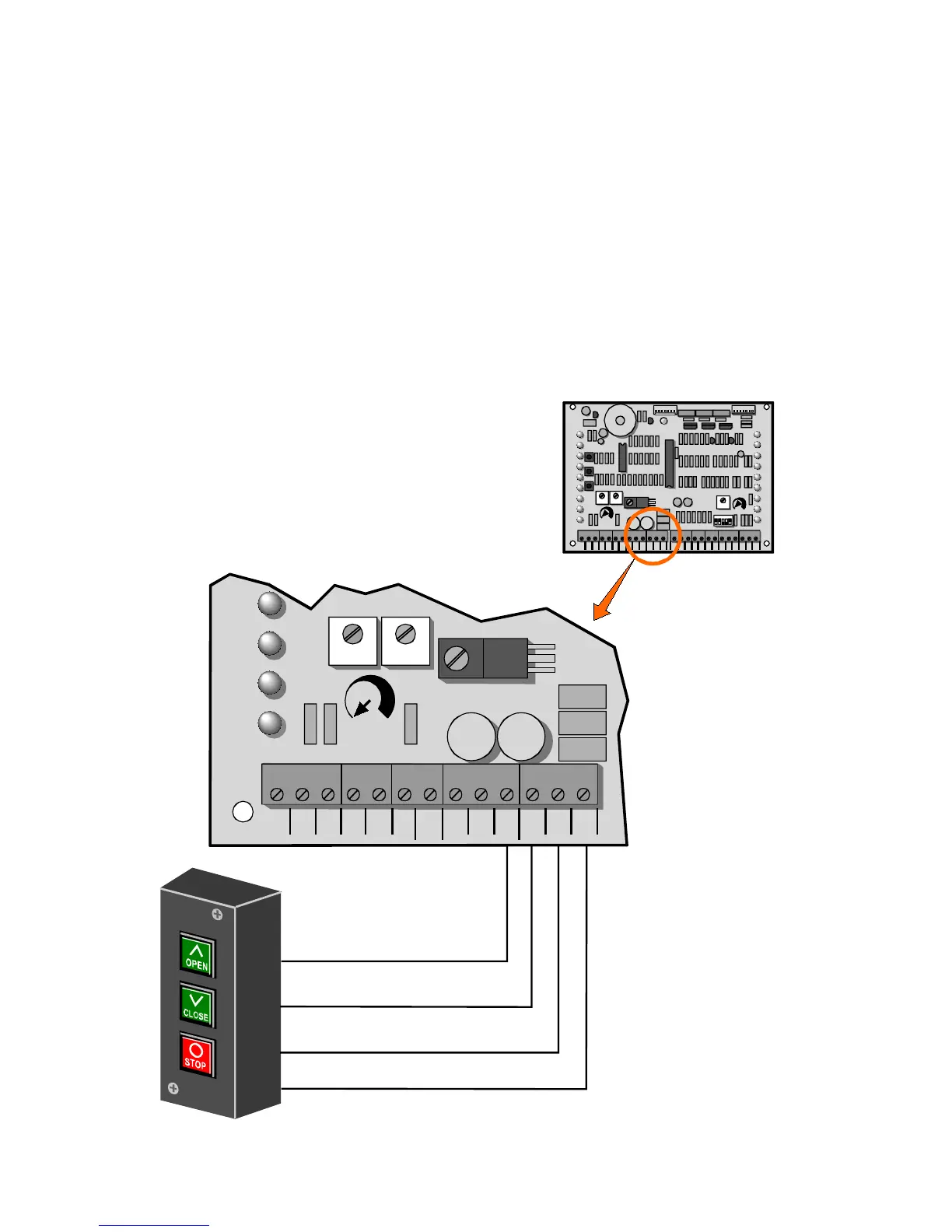
1. Connect a wire from the common connection of the control
station to any “COM” terminal on the control board.
2. Connect a second wire from the “OPEN” button of the control
station to the “OPN” terminal on the control board.
3. Connect a third wire from the “CLOSE” button of the control
station to the “CLO” terminal on the control board.
4. Connect a fourth wire from the “STOP” button of the control
station to the “STO” terminal on the control board.