EasyManua.ls Logo

PowerMaster SG 2004 - LOOP INSTALLATION

Default Icon
52 pages
Print Icon
To Next Page IconTo Next Page
To Previous Page IconTo Previous Page
Loading...
LOOP INSTALLATION
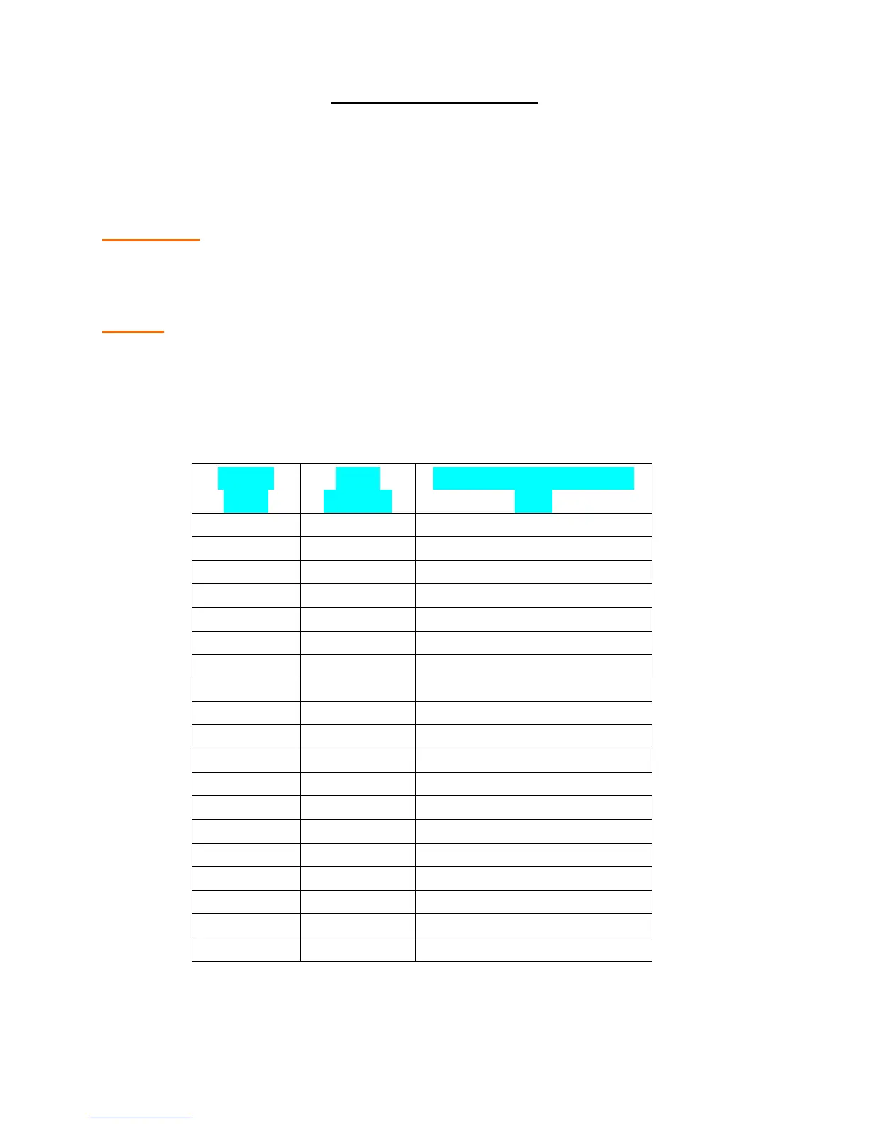
1. Layout the desired loop locations per the diagram. The standard size
chart below will give an approximate length of wire required for
various loop dimensions and number of turns required.
CAUTION: The Loop wires and Lead-in wires must be a continuous
piece of wire without splices. Only use wire intended for this type of
application. (Type XHHW insulation 16AWG)
NOTE: Buried steel from drains or other systems may affect functioning of
the loop system. Check with the factory for advice on any special
installations. (1-800-243-4476).
STANDARD LOOP LAYOUTS
FOR APPROX 36” HEIGHT DETECTION
LOOP
SIZE
# OF
TURNS
LOOP WIRE LENGTH
(FT)
4’X4’
4
64’
4’ X 6’
4
80’
4’ X 8’
3
72’
4’ X 10’
3
84’
4’ X 12’
3
96’
4’ X 14’
3
108’
4’ X 16’
3
120’
4’ X 18’
3
132’
4’ X 20’
3
144’
4’ X 22’
3
156’
4’ X 24’
3
168’
4’ X 26’
3
180’
4’ X 28’
3
192’
4’ X 30’
2
136’
4’ X 32’
2
144’
4’ X 34’
2
152’
4’ X 36’
2
160’
4’ X 38’
2
168’
4’ X 40’
2
176’

Other manuals for PowerMaster SG 2004

Related product manuals