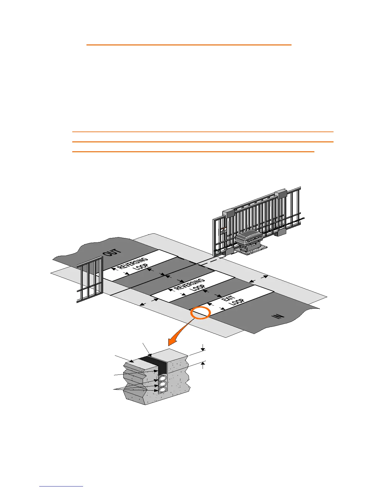
LOOP DETECTOR SYSTEMS AND INSTALLATION
The diagram below depicts the typical loop options for a Slide Gate
installation.
1. The Exit Loop provides a signal to open the gate when a vehicle
enters the loop zone.
2. The Reversing Loops protect a vehicle in the loop zone from
being contacted with the gate by overriding any close signal
while the gate is open, and by reversing the gate if closing.
4'
4'
4'
4'
4'
4'
4'
4'
Road Surface
Sealant
Loop wires
Min 1"
3/16" To 1/4"
Saw Slot