Do you have a question about the Powermatic 26 and is the answer not in the manual?
Follow manual instructions, protect yourself, give work attention, maintain balance, use eye protection, and wear appropriate clothing.
Keep the work area clean, free of debris, and well-lit to prevent hazards like tripping or slipping.
Ensure guards are in place, start switch is off before power connection, and machine is locked out for maintenance.
Ensure the machine is properly electrically grounded according to the National Electric Code for safety.
Follow stock length rules, keep hands clear of cutters, use safe hand movements, and feed stock opposite cutter rotation.
Utilize templates for blind cuts and guide pins for pattern or collar shaping for improved safety and accuracy.
Maintain sharp tools and check cutter clearance and spindle rotation direction before operation for safety.
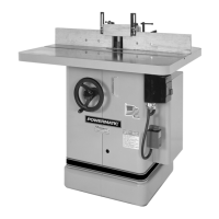
Know the limitations and hazards associated with the Model 26 shaper; heed safety decals.
Ensure safety lock washer is used, do not exceed rated spindle speeds, and use only safety type cutters.
Be aware of stock conditions like knots or warping that can cause kickback; prepare stock properly.
Turn off the shaper before leaving; avoid reaching over the shaper due to kickback danger; use push sticks.
Use only POWERMATIC or factory authorized replacement parts and accessories to maintain warranty.
Decal lists rules: read manual, operate with guards, grounding, secure clothing, use eye protection, stop before adjustments, keep area clean.
Danger decal warns to turn cutter by hand to check for interference before connecting power to avoid injury.
Provides physical dimensions like table size, height from floor, and spindle opening diameter.
Lists available spindle types (interchangeable, stub, solid) and their capacities under the nut.
Specifies spindle travel distance and available spindle speeds (RPM).
Indicates the weight of the machine, including the 2hp motor, in pounds and kilograms.
Identifies key components of the quill slide assembly in a diagram.
Shows the base and motor as integral parts of the quill slide system.
Illustrates the handwheel and pinion shaft used for operating the quill slide.
Mount the shaper base to the floor using high-quality anchor bolts for stability.
Attach and tighten the drive belt, ensuring proper tension by checking belt depression between pulleys.
Check voltage and phase; ensure the machine is properly grounded by a qualified electrician to avoid shock.
Check all mounting screws and bolts to ensure they are securely locked before connecting power.
The spindle and quill assembly have permanently sealed bearings; lubrication is not necessary.
Turn the spindle by hand to verify it rotates freely without binding.
Inspect for loose or worn electrical connections within the electrical enclosure.
Check that the two mounting screws holding the fence assembly to the table are tight.
Ensure the four countersunk flathead bolts holding the wooden fences are tight.
Clamp a jointed 2x4 board to the table to check if the fence is parallel with the miter groove.
Loosen the two lock handles on the fence assembly to allow for adjustment.
Select the correct hole in the shaper wrench and place it over the spindle flats for removal.
Place a wrench on the drawbar nut and turn it counterclockwise while holding the spindle stationary to remove it.
Remove the spindle vertically and replace it with the size of your choice.
First, remove the drive belt from the spindle sheave before proceeding with removal.
Loosen the split casting locking screw to free the spindle assembly.
Remove the spindle assembly by pulling it out from the bottom of the shaper.
Select the proper rectangular hole in the shaper wrench and place it over the spindle flats.
Place a wrench on the 3/4 inch spindle nut and turn it counterclockwise while holding the spindle stationary.
Remove the spindle nut and the slotted washer after loosening.
Remove the cutter(s) vertically and replace them with the size of your choice.
Disconnect power from the machine before attempting to change speeds.
Roll the belt off one pulley to the other on the motor side to adjust speed.
Rotate the pulley and roll the belt until it snaps into the groove of the other spindle pulley.
The miter gauge is used for accurate end grain cutting and handling specific parts.
Adjust stops to 90 and 45 degrees using a combination square, screwdriver, and wrench.
Remove the two 3/8" x 1" socket head cap screws to detach the fence assembly.
Store the fence assembly safely and clean it before re-mounting it on the table.
Check motor and switch wiring diagrams for proper voltage connections before applying power.
Turn the motor momentarily to check for proper spindle rotation (counterclockwise when viewed from above).
Run the machine briefly to ensure moving parts work properly with no excessive vibration; correct any problems.
| Brand | Powermatic |
|---|---|
| Model | 26 |
| Category | Power Tool |
| Language | English |