Do you have a question about the Powermatic 45 and is the answer not in the manual?
Prioritize reading safety and operating instructions before using the machine.
Details the manufacturer's warranty terms and conditions for the lathe.
Covers personal protection, work area, tool condition, and workpiece checks.
Adheres to speed, tool usage, measurement, and attention requirements.
Includes safety during maintenance, machine securing, and motor limits.
Emphasizes using authorized parts and operating for intended purposes only.
Presents lathe specifications in English and Metric units.
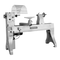
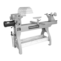
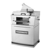
Illustrates the lathe's physical dimensions and floor plan layout.
Provides RPM recommendations for various work diameters and cutting types.
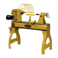
Instructions for receiving, mounting, grounding, and initial setup of the lathe.
Covers motor inspection, rotation, switch locations, and safety.
Detailed steps for adjusting the belts on the variable speed drive.
Instructions for adjusting belt tension on step cone models using a cam.
Procedure for removing the headstock spindle for maintenance tasks.
Guidance on tool rest adjustment, cleaning, and proper movement.
Specifies periodic lubrication for bearings, screws, and other parts.
Procedures for maintaining the tailstock, including cleaning and lubrication.
Addresses causes and remedies for excessive vibration and motor/spindle stalls.
Solutions for motor overheating, slow start, low power, and speed control problems.
Remedies for tools digging in and the lathe running at a single speed.
Illustrates the electrical schematic for control and motor circuits.
Lists electrical parts, numbers, and quantities for the lathe.
Diagrams for manual, magnetic, and low voltage control systems.
Shows transformer connections for 230V and 460V primary voltages.
Lists components for manual control systems, including switches and starters.
Lists magnetic control parts, transformers, and motors.
Diagram and parts list for the lathe's stand and bed assembly.
Exploded view illustrating the components of the variable speed head.
Comprehensive list of parts for the variable speed head area.
Exploded view illustrating the components of the step cone head.
Comprehensive list of parts for the step cone head area.
Diagram showing the components within the step cone drive area.
Comprehensive list of parts for the step cone drive area.
Diagram showing the components within the variable speed drive area.
Comprehensive list of parts for the variable speed drive area.
Diagram and parts list for the tailstock assembly.
Diagram and parts list for the tool rest assembly.
Diagram and parts list for the guard assembly.
Diagram and parts list for optional metal spinning tool rests and kits.
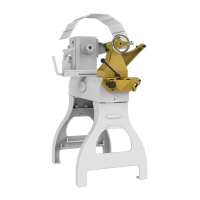
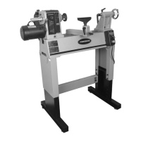
Diagram and parts list for the optional outboard turning stand assembly.
| Type | Wood Lathe |
|---|---|
| Motor Power | 1 HP |
| Model | 45 |
| Spindle Taper | MT2 |
| Tailstock Taper | MT2 |
| Motor | 1 HP, Single Phase |