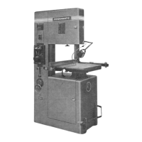
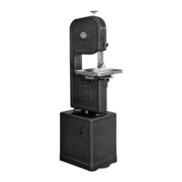
Model 87
20"
Metal Cutting Band Saw
OPERATING INSTRUCTIONS
OPERATING INSTRUCTIONS
The
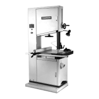
Powermatic Model 87-20" Metal Cutting Band Saw
is
constructed
of
steel plate, braced to give maxi-
mum
rigidity. Streamlined in appearance,
all
movin;) parts are completely guarded for ' safe operation.
The
top and bottom band wheels are eaSily
accessib~e
through large hinged doors
on
front
of
the saw.
Sealed dust chute keeps motor and drive free from cuttings and dust.
MOTOR
AND
WIRING: Electric wiring
is
connected b a motor wiring
in
conduit box mounted
on
the side
of
the column.
Motor
should be inspected and checked for rotation before operating machine.
Operate
lower unit and check rotation before installing blada. Frame
of
machine should ALWAYS be grounded.
POWER
DRIVE:
The
saw
is
driven with a motor fastened
on
an adjustable hinge base mounted
in
the
base
of
the machine. A motor from 1
Y2HP,
single or 3-phase
is
available; 1
Y2
HP
for light work
and
1
Y2
HP
to 3
HP
for medium to heavy work
is
recommended. Two A section belts drive the lower band wheel.
INSTALLING
BLADE:
To
install band saw blade: remove
table
insert (19) Fig.
1,
from
table
; open top and
bottom doors. Take the blade
in
both hands and slide through
table
slot and over band wheels.
With
blade
placed
in
the center
of
the band wheels, increase tension on upper wheel with tension screw (16)
Fig.
5,
located under upper wheel.
Set
upper and lONer saw guides
so
they will clear the saw
blade
.
Turn band wheels by hand to
see
that saw
blade
tr::Jcks
properly
. It
is
important
that
the
blade
runs
centered
on
the wheels for accurate work and maximum.
blade
life. When the adjustment has been prop-
erly
made, the
blade
will track; that
is,
it will run staadily
in
the same line.
BLADE
TENSION: Correct
blade
tension
is
very important for efficient operation.
The
wider
and
thicker
blades require more tension than narrow blades. A graduated tension indicator for
different
blade
widths (
17
) Fig. 5,
is
located inside the frame and bahind upper wheel. Tension
is
regulated
by
screw
(
16
)
Fig
. 5, maintaining pressure on tension spring.
The
spring
is
designed to give correct tension
only
for standard gauge blades. Tension may vary for heavier
and/or
thicker blades. Blade tension does
not vary with length
of
blade
.
WHEEL
ALIGNMENT: Band wheels are properly ali;)ned
at
the factory and should operate correctly.
However, in shipping, the original adjustments
mal
have moved, necessitating realignment. The lower
wheel housing
is
1l1..0unted
on
jack screws,
two
in
the rear
and
two
in
the front.
The
shaft may be leveled
by
loosening the two bearings locking bolts and adjusting the two jack screws. Bearing bolts should be
retightened
after
shaft
is
leveled.
BLADE
GUIDE ADJUSTMENT:
For
proper operation, the saw
blade
must be supported
by
an
upper
and
lower saw guide.
The
lower guide
is
mounted under the
table
and the upper guide on a counterbal-
anced
bar
above the
table
(18) Fig.
5.
The
purpose
of
the saw guides
is
to support the
blade
for
cutting
curve surfaces. It
is
very IMPORTANT
for
the guides
to
be adjusted in proper relation
to
saw blades.
Before adjusting guides, adjust tension on blade, start motor and check tracking on band wheels. Stop
Motor-take
no chances. Adjust the side blocks
or
bearings (both
upper
and lower)
to
saw blades,
leaving a little clearance on each side.
The
thickness
of
a piece
of
paper
is
a good clearance
gauge
(20) Fig. 2. Guide blocks
or
bearings are held in place with socket head set screws
(9)
Fig. 2
and
can
easily be adjusted.
After
blade
clearance
is
set,
the back guide holder should be adjusted with the
knurled knob (8)
Fig
. 4
so
the edge
of
the side guides
is
just behind saw teeth gullets (21) Fig. 4. The
back guide consists
of
a ball bearing mounted on
an
adiustable
bar
(22) Fig. 4
and
should be set
1/64",
or
thickness
of
a piece
of
paper, from back edge
of
the blade.
The
back guide
is
set
at
a slight
angle
to
back
of
blade
so
the edge
of
the
blade
will
not cut a groove in back bearing guide. For best opera-
tion, the LOWER saw guide
(7)
Fig. 1 should be set
as
CLOSE
as
possible
to
bottom
of
table. To adjust
the lower guides, loosen guide bolts
(6
) Fig. 1 and ra ;
se
the guide
as
close
as
possible
to
bottom
of
table.
Tighten guide bolt.
TABLE
ADJUSTMENTS:
The
table
is
mounted on an extremely heavy
duty
. single action trunnion
that
rests
on
trunnion base (23)
Fig
. 1.
The
table
may
be
tilted
to
the right 45 degrees and
to
fhe left
15
degrees. Table
is
locked in position with trunnion h :lndwheel mounted on side
of
machine base (
5)
Fig.
1.
To
tilt
table, turn handwheel
to
left about
Y2
turn, and
tilt
the
table
to
the desired
angle-tighten
trunnion.
To
level
table
with blade, raise counterbalanced arm
to
highest position and place machinist
square against side
of
blade. Set
table
stop (24) Fig. 6,
on
side
of
table
by
adjusting screw on
top
of
the stop. Stop
bar
should be removed
for
tilting to ble to the left.
LUBRICATION:
The
bearings on top and bottom
sha
ft
are sealed
for
life, requiring no lubrication.
The
slides and adjusting screws should be lubricated
at
regular intervals
to
insure proper operation. Va-
riable speed transmission
is
filled with
3Y2
quarts
of
40
or
50 weight motor
oil-DO
NOT
use
transmis-
sion
orease-keep
oil to top
of
elbow
on
oil
filler
pipe.
TRANSMISSION
OPERATION:
To change speed
ra
nge
of
transmission, turn
variable
speed hand wheel
(15)
Fig. 6
to
slow speed.
Pull
the lock pin shiftil'lg handle
(13)
Fig. 6
to
the
right
for
slow speed,
left
for
high speed ond center
for
neutral.
To
obtain
maxi mum variable speed range, the varioble sheaves
must be
properly
adjusted. To adjust belt, set hand wheel
(15)
Fig. 6
to
slow range and remove
bolt
(I)
Fig. 3. Turn turnbuckle
(2)
Fig. 3
to
right
to
raise
belt
in
upper
variable
speed pulley and
to
left
to
lower.
When
belt
is
properly
adjusted,
it
will ride flush with the
top
of
the
upper
pulley in the slow
speed range and flush with the
top
of
the lower
pulley
in the high speed range.
POWER
FEED
OPERATION:
To
operate
power
feed,
push
foot
pedal down until latched. Place mate-
rial
to
be
cut
against feed block and
push
up
to
blade. The material does
not
have
to
be
"squored"
in
relation
to
material guide. Fasten the chain hook, Part 87-615,
to
the chain 87-616, place chain in chain
segments 87-609. The cables and chain can be
adjust~
for
various
sizes
by
odjusting the
power
feed
wheels
(10)
Fig. 7
either
in
or
out. The
two
power
feed
wheels can be
adjust~d
independently
. To
change
feed
rate, move
weight
toward
linkage
to
increase feed rate,
toward
hinge pin
to
decreose
feed
rate. Start the
saw
and release the latch on
foot
pedal.
POWERMATIC/HOUDAILLE,
McMinnville,
Tennessee
PAGE 3
 Loading...