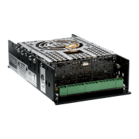
11 Failure of the MOSFETs
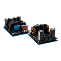
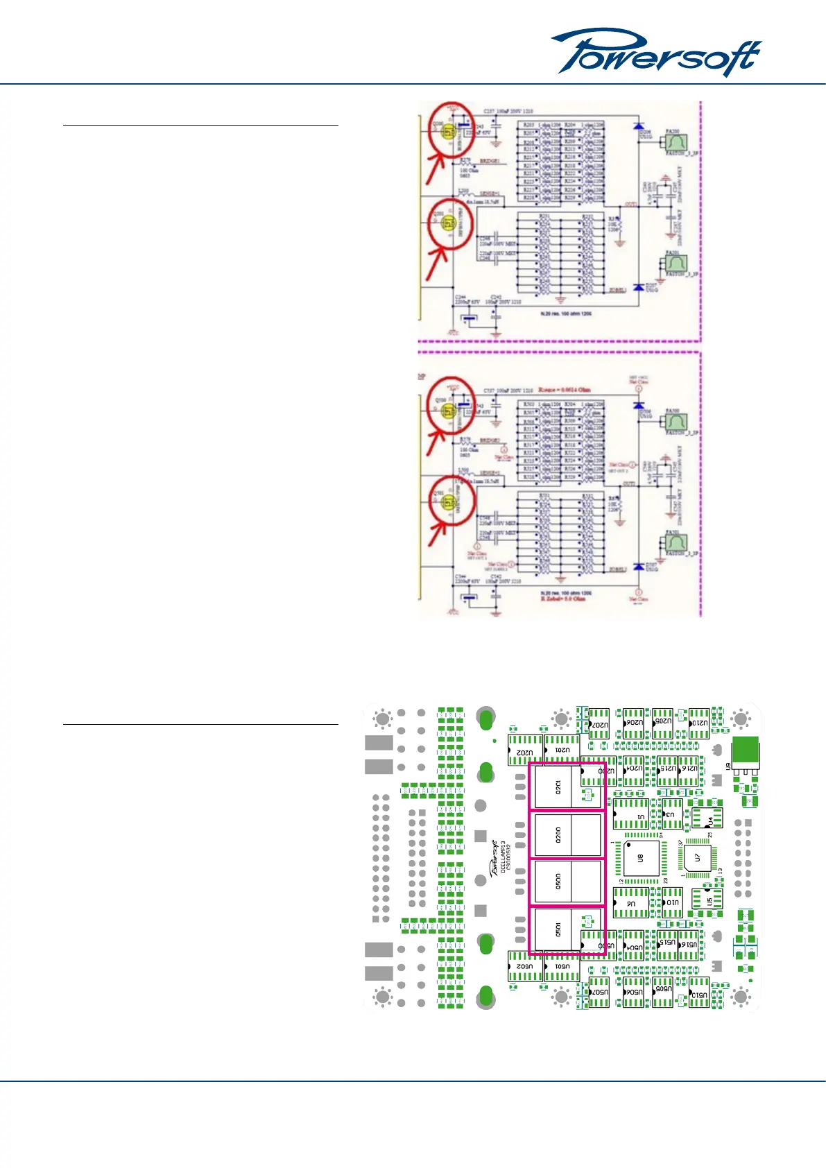
1. The MOSFETs are located on the bottom side of
the amplier’s PCB.
2. Components to be replaced:
f Channel 1 MOSFETs Q200, Q201
f Channel 2 MOSFETs Q500, Q501
We recommend to carefully position the Sil-Pads to
ensure the proper heat exchange between the com-
ponents and the chassis.
12 Further tests
1. After checking and replacing all the defective
components, try to test the module applying an
incremental voltage through a variac.
2. Connect the probes of your multimeter to the
CN800T connector on the power supply board;
with respect to ground:
f on pins 1 to 4 sense +V
CC
,
f on pins 12 to 16 sense –V
CC
.
3. The unit should start to work at about 90 V
AC
. The
Rail voltages ±V
CC
must be about ±40V
DC
.
FIGURE 14: MOSFETs.
FIGURE 13: Output MOSFETs on the bottom side of the PCB.
9