UNPACKING
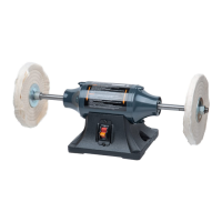
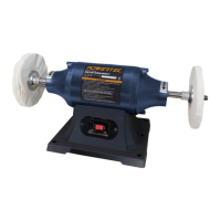
Refer to Figure 1
• Check for shipping damage. Check immediately whether all
parts and accessories are included. The bench buffer itself
comes assembled as one unit. Additional parts (listed below)
which need to be fastened to bench buffer, should be located
and accounted for before assembling.
• The following items are included with your bench buffer:
Item Description Qty.
A
Buffer
1
B
Flanges
4
C
Spacers
2
D
Arbor Nuts (left M16LH and right M16RH)
2
E
Buffer Wheels
2
Figure 1
A
BC D
E
LEFT RIGHT
E
• Carefully remove the tool and any accessories from the box.
• Make sure that all items listed in the packing list are included.
• Inspect the tool carefully to make sure no breakage or damage
occurred during shipping. Do not discard the packing material
until you have carefully inspected and satisfactorily operated
the tool.
CAUTION
Do not attempt assembly if parts are missing. Call the Customer
service line to obtain replacement parts.
WARNING
Do not operate bench buffer, until completely assembled.
Do not operate this tool until you have completely read
and understood this manual.
WARNING
To avoid injury, make sure all parts are assembled and
adjusted properly before plugging the bench buffer into a
power outlet and turning it ON.
ASSEMBLY
3
TOOLS NEEDED
You will need the following tools to assemble and adjust the
machine. (The tools are not included.)
• 15/16 open end or adjustable wrench
• 1/2" wrench
SET UP
WARNING
Always place the ON/OFF switch in the OFF position
and unplug the power cord from its power source before
performing any assembly or adjustment. Failure to do so
could result in accidental starting resulting in possible serious
personal injury.
WARNING
To prevent serious injury from accessory failure. Do not use
grinding wheels or other unintended accessories with this
bench buffer.
NOTE: "LEFT" and "RIGHT" are as seen from in front of the
bench buffer, facing the switch.
TO ASSEMBLE THE BUFFER WHEELS
1. Remove the packaging sleeves (if equipped) from
the shafts.
2. Slide the spacer onto the shaft. NOTE: The spacers are
not always needed, for example when using thicker wheels.
The purpose of the spacers is to set the flanges and wheels
away from the step in the shaft, allowing the arbor nuts to be
threaded onto the shafts to secure the wheels in place.
Figure 2
Spacer
Arbor Nut
Flange
(cupped side to
buffing wheel)
Flange
(cupped side to
buffing wheel)
3. Slide the inner flange onto the shaft with the cupped side
facing the threaded end of the shaft. The cupped side will be
against the buffing wheel when assembled.
4. Slide the buffing wheel onto the shaft and up against the
inner flange.
5. Slide the outer flange onto the shaft and up against the
buffing wheel. The cupped side should be facing towards
the buffing wheel.
3
ASSEMBLY