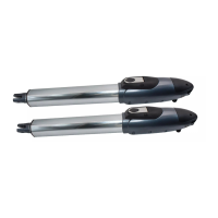
ARTICULATED ARM OPENERS USER MANUAL
4
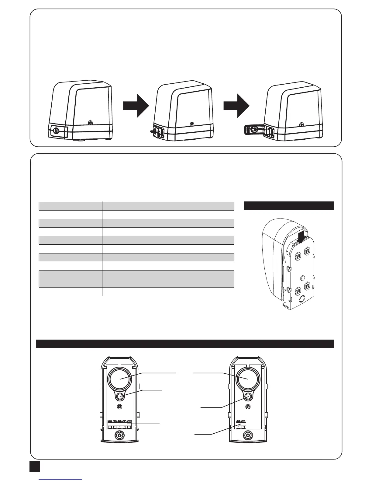
1.2.5 Emergency Release
1) Insert the release key to the release slot
2) Turn the release key anti-clockwise
3) Pull out the release bar
4) Turn the release key clockwise to fix the release bar, the release bar has to be in pulled out position when turning
the release key clockwise
The safety photocells are security devices for control automatic gates. Consist of one transmitter and one receiver
based in waterproof covers; it is triggered while breaking the path of the beams.
INSTALLATION:
Wire Connection of Photocells
TX: Connect terminals 1 and 2 on the transmitter with the terminals GND and PhVcc on the PC190 PCB.
RX: Connect terminals 1,2 and 4 on the receiver with the terminals GND, PhVcc, and Ph1/Ph2 on the PC190 PCB.
And use an extra wire to connect terminals 2 and 5 on the receiver as a bridge.
Detection Method
Sensing Range
Input Voltage
Response Time
Emitting Element
Operation Indicator
Dimensions
Output Method
Current Consumption Max
Water Proof
Through Beam
25M
AC/DC 12~24V
100MS
IR LED
Red LED(RX): ON(When Beam is Broken), Green(TX):ON
96*45*43mm
Relay Output
TX: 35MA/Rx: 38MA (When beam aligned properly);
TX: 35MA/ Rx: 20MA (When beam is broken)
IP54
SPECIFICATION:
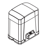
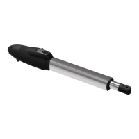
Figure 1(2)
Figure 1(1)
1.2.6 Photocell Installation
RX
Lens
Beam Alignmnet
Indicator
Power Led
Indicator
Terminal Block
Power
Terminal Block
TX
1 2 3 4 5 1 2