INSTRUCTIONS PW150/PW200
1
Index
1. Warnings
2. Product Description
2.1 Applications
2.2 Description of The Automation
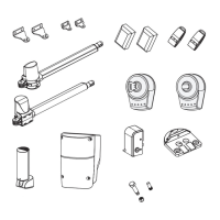
2.3 Description of Devices
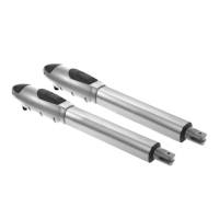
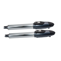
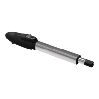
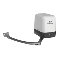
2.3.1 PW150/PW200 Electromechanical
Gear Motors
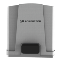
2.3.2 Control Box
2.3.3 PH-1 Photocells
2.3.4 PKS-1 Key Selector
2.3.5 PPB-1 Push Button
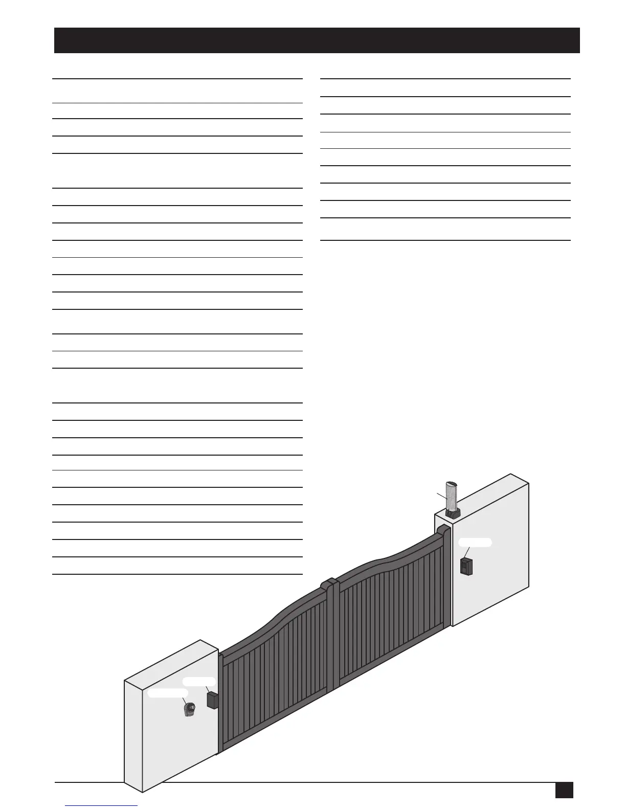
2.3.6 PF-1 Flashing Light
2.3.7 PR-1 Radio Transmitter
2.3.8 PEL-1 Electric Latch and PS-1 Stopper
3. Installation
3.1 Notes of Motors in Operation
3.1.1 Tools in Installing
3.1.2 Motors, Components and Its Installation
in Illustration
3.2 Power Connection
3.2.1 Notes for Power Connection
3.3 Installation
3.3.1 Preparation for Motor Installation
3.3.2 Installation of The Gear Motors
3.3.3 PKS-1 Key Selector
3.3.4 PPB-1 Push Button
3.3.5 PF-1 Flashing Light
3.3.6 PH-1 Photocells
3.3.7 PEL-1 Electric Latch and PS-1 Stopper
4. Technical Characteristics
4.1 PW150
4.2 PW200
4.3 PH-1 Photocells
4.4 PKS-1 Key Selector
4.5 PPB-1 Push Button
4.6 PF-1 Flashing Light
4.7 PR-1 Transmitter
4.8 PEL-1 Electric Latch
5. CE Declaration of Conformity
2
3
3
3
3
4
4
4
4
5
5
5
5
5
5
6
6
6
6
7
7
9
11
12
12
13
14
16
16
16
16
16
16
17
17
17
18
Flashing Light
Photocell
Photocell
Key Selector