Installation
28
Powerware
®
9150 User’s Guide
:
www.powerware.com
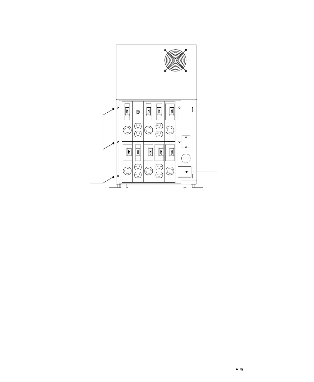
Screws from
UPS panel; 3 on
each side
reused for PDM
WireCover for
Output Conduit
Landing
Figure 10. Mounting the PDM to UPS Rear Panel
7. Insert the bushing (provided with the PDM packaging) into the
output conduit landing.
8. Hardwire the input (TB1-1 through TB1-4) terminations for the
UPS. See the following hardwired terminations table for
specifications. See Figure 11 for a detailed view of the terminal
blocks.
9. Insert the wires from the PDM into the output conduit landing
and connect to the UPS terminal block according to the
following table.