Installation
29
Powerware
®
9150 User’s Guide
:
www.powerware.com
Powerware 9150 Hardwired Terminations for Optional PDM
WireFunction
Terminal U
stream
ConduitConnection
Input
Position*
CircuitBreaker
Suggested Wire Size**
(EntrySize)
Ground
TB1-1 8AWG
L1/A TB1-2
70A
4AWG
1-3
4
2
access hole for
L2/B
TB1-3
70A
4AWG
1-1/4
2
conduit
Neutral
TB1-4 2AWG
OutputforPDM Wire Color
Ground TB1-6 Green/Yellow
L1/A TB1-7 Black
1-3
4
2
access hole for
L2/B
TB1-8 Red
1-1/4
2
conduit
Neutral
TB1-9 White
*All terminal wire size ratings are 8- 4 AWG, except TB1-4 is 8 - 1/0.
**Use 75
C copper wire. Suggested wire size is based on 120/208 full load ratings applied to NEC Code Table 310-16.
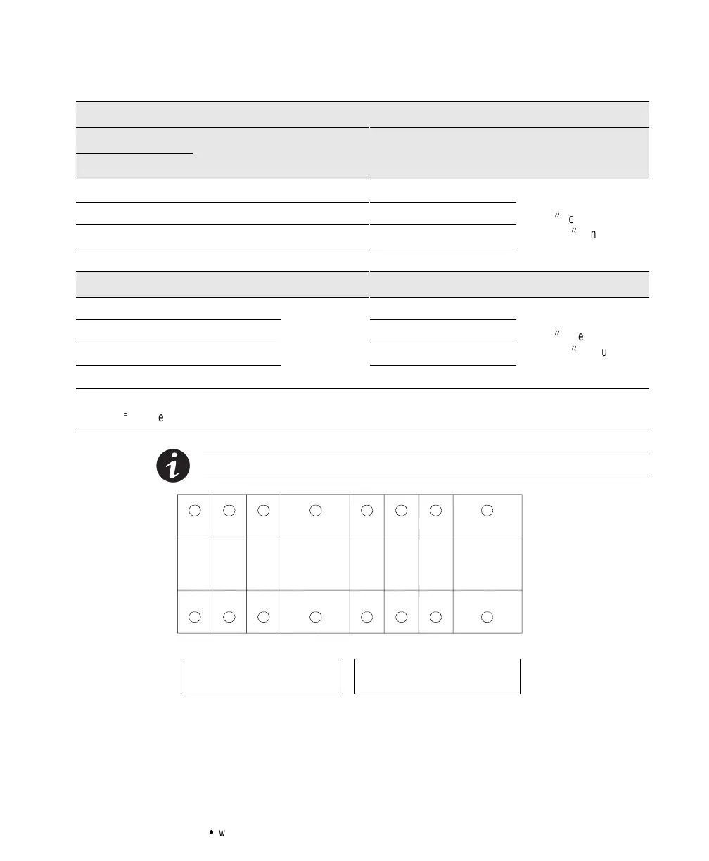
NOTE Proper phaserotationmustbe observed.
123 4 678 9
Ground L1/A L2/B N Ground L1/A L2/B N
Input Output
Figure 11. Hardwired Terminal Blocks